HCD-GPZ6/GPZ7
1919
HCD-GPZ6/GPZ7
SECTION 6
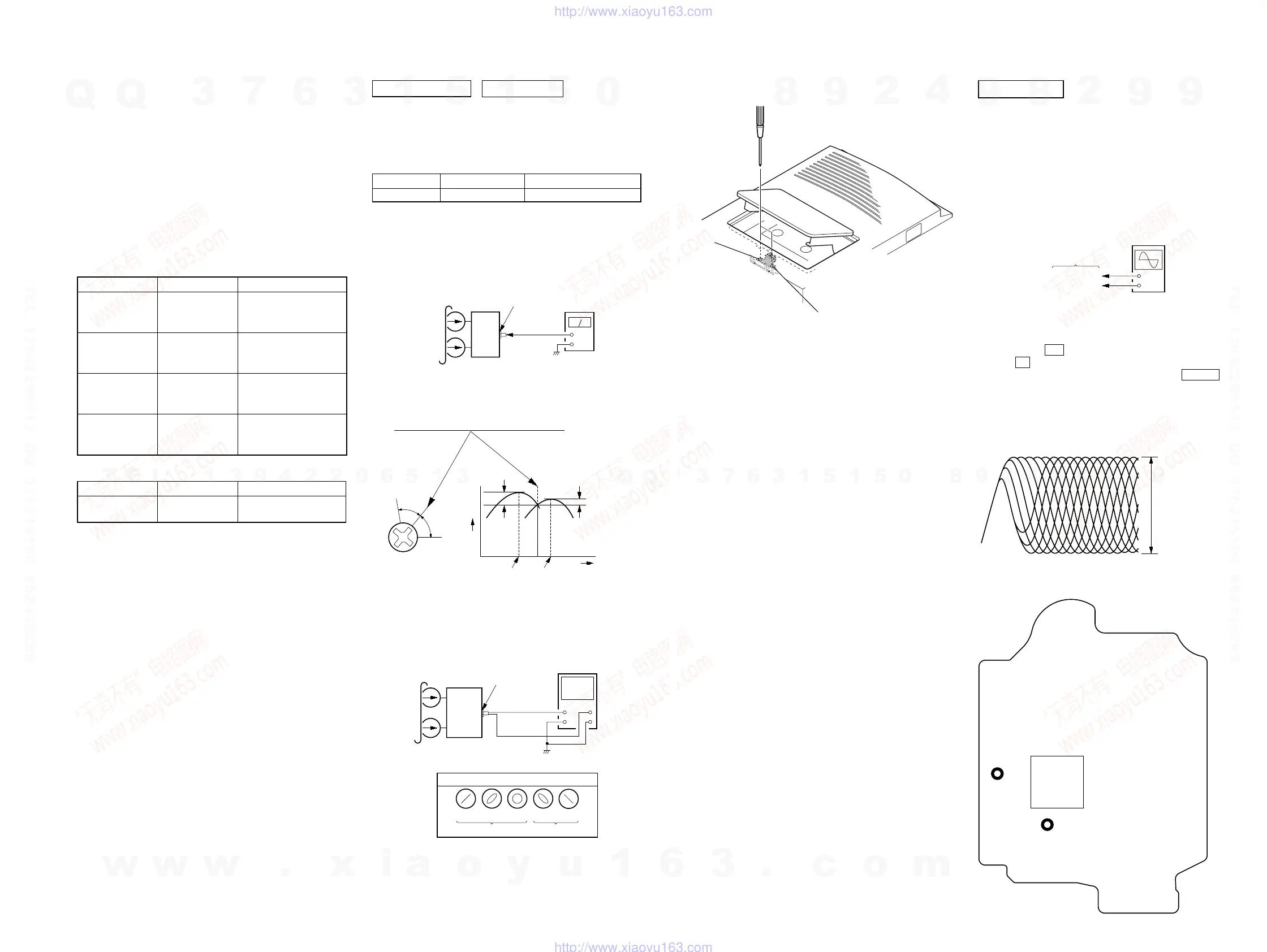
ELECTRICAL ADJUSTMENTS
Screw
position
L-CH
peak
within
1dB
Output
level
L-CH
peak
R-CH
peak
within
1dB
Screw
position
R-CH
peak
0 dB=0.775 VDECK SECTION
set
PANEL (2) board
PHONES jack
(J321)
+
–
level mete
test tape
P-4-A063
(6.3 kHz,
−
10 dB)
1. Demagnetize the record/playback head with a head
demagnetizer.
2. Do not use a magnetized screwdriver for the adjustments.
• Test Tape
RECORD/PLAYBACK HEAD AZIMUTH ADJUSTMENT
Procedure:
1. Mode: Playback
2. Turn the adjustment screw and check output peaks. If the peaks
do not match for L-CH and R-CH, turn the adjustment screw
so that outputs match within 1dB of peak.
3. Mode: Playback
4. After the adjustments, apply suitable locking compound to
the pats adjusted.
Tape Signal Used for
P-4-A063 6.3 kHz, -10 dB Azimuth Adjustment
set
test tape
P-4-A063
(6.3 kHz,
−
10 dB)
oscilloscope
V
H
waveform of oscilloscope
in phase 45
°
90
°
135
°
180
°
good
wrong
PANEL (2) board
PHONES jack
(J321)
Checking Location:
+
–
BD board
TP (RFACI)
TP (VC)
oscilloscop
(DC range)
Procedure :
1. Connect oscilloscope to TP (RFACI) and TP (VC) on the BD
board.
2. Press the I/1 button to turn the power ON, and press
the Z (CD) button to open the CD disc tray.
3. Set disc (YEDS-18) on the tray and press the CD u button
to playback.
4. Confirm that oscilloscope waveform is as shown in the figure
below. (eye pattern)
A good eye pattern means that the diamond shape (◊) in the
center of the waveform can be clearly distinguished.
VOLT/DIV: 200 m
TIME/DIV: 500 ns
level:
0.9
±
0.4 Vp-p
TP
(VC)
TP
(RFACI)
IC201
– BD Board (Conductor Side) –
CD SECTION
Note:
1. CD Block is basically constructed to operate without adjustment.
2. Use YEDS-18 disc (3-702-101-01) unless otherwise indicated.
3. Use an oscilloscope with more than 10 MW impedance.
4. Clean the object lens by an applicator with neutral detergent when the
signal level is low than specified value with the following checks.
5. Check the focus bias check when optical pick-up block is replaced.
FOCUS BIAS CHECK
Adjustment Location: Record/Playback/Erase Head
SECTION 5
MECHANICAL ADJUSTMENTS
• Precaution
1. Clean the following parts with a denatured-alcohol-moistened
swab :
record/playback head pinch roller
erase head rubber belts
capstan idlers
2. Demagnetize the record/playback head with a head
demagnetizer. (Do not bring the head magnetizer close to the
erase head.)
3. Do not use a magnetized screwdriver for the adjustments.
4. After the adjustments, appiy suitable locking compound to
the parts adjusted.
5. The adjustments should be performed with the rated power
supply voltage unless otherwise noted.
• Torque Measurement
Mode Torque Meter Meter Reading
2.95 – 6.86 mN⋅m
FWD CQ-102C (30 – 70 g⋅cm)
(0.42 – 0.97 oz⋅inch)
FWD
0.15 – 5.39 mN⋅m
Back Tension
CQ-102C (1.5 – 5.5 g⋅cm)
(0.021 – 0.076 oz⋅inch)
more than 5.89 mN⋅m
FF CQ-201B (more than 60 g⋅cm)
(more than 0.83 oz⋅inch)
more than 5.89 mN⋅m
REW CQ-201B (more than 60 g⋅cm)
(more than 0.83 oz⋅inch)
• Tape Tension Measurement
Mode Tension Meter Meter Reading
FWD CQ-403A
more than 100 g
(more than 3.53 oz)
reverse
forward
w
w
w
.
x
i
a
o
y
u
1
6
3
.
c
o
m
Q
Q
3
7
6
3
1
5
1
5
0
9
9
2
8
9
4
2
9
8
T
E
L
1
3
9
4
2
2
9
6
5
1
3
9
9
2
8
9
4
2
9
8
0
5
1
5
1
3
6
7
3
Q
Q
TEL 13942296513 QQ 376315150 892498299
TEL 13942296513 QQ 376315150 892498299
http://www.xiaoyu163.com
http://www.xiaoyu163.com