SECTION 6
DIAGRAMS
6-1. CIRCUIT BOARDS LOCATION
PANEL board
TRANS board
SURROUND board
MAIN board
POWER board
CD-B1 SW board
CD-B2 SW board
TC-B SW board
DOOR SW board
CD-LED board
TC-A SW board
HP/MIC board
LEAF SWITCH board
BD board
LED board
CD MOTOR board
TABLE SENSOR board
— 17 —
— 18 —
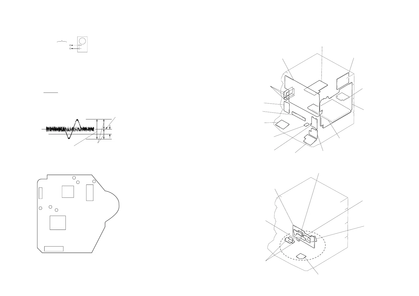
E-F Balance (1 Track Jump) check
oscilloscope
BD board
TP (TEO)
TP (VC)
Procedure:
1. Connect oscilloscope to test point TP (TEO) on BD board.
2. Turned Power switch on.
3. Put disc (YEDS-18) in to play the number five track.
4. Press the “P (Pause)” button.
5. Check the level B of the oscilloscope's waveform and the A (DC
voltage) of the center of the Traverse waveform.
Confirm the following:
• x 100 = less then ± 7 (%)
• A + B = 500 ± 100 mVp-p
A – B
2 (A + B)
1 track jump waveform
0V
Center of the waveform
B
A (DC voitage)
Symmetry
level : 500 mV ± 100 mVp-p
Adjustment Location:
[BD BOARD] (Conductor Side)
TP (RF)
TP
(FOK)
TP
(VC)
IC101
TP
(TEO)
TP
(FEO)
TP
(GND)
IC103
IC102
CN101
IC102
CD-A SW board
TCB board (AEP, UK, East European, CIS)
FM/AM TUNER PACK
(ENCAPSLATED COMPONENT)
(EXCEPT AEP, UK, East European,
CIS)
AUDIO board
(including
p
A)
p
A
MOTOR board
Note: pA is including in AUDIO board.
www.freeservicemanuals.info



 To Next Page