1 (E)
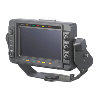
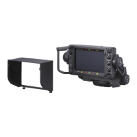
HDVF-C950W
Table of Contents
Manual Structure
Purpose of this manual ........................................................... 3 (E)
Relative manual ...................................................................... 3 (E)
1. Service Overview
1-1. Board Layout ........................................................... 1-1 (E)
1-2. Matching Connectors and Cables ............................ 1-1 (E)
1-2-1. Cable Input/Output Signals ............................ 1-1 (E)
1-2-2. VF Connecting Cable ..................................... 1-2 (E)
1-3. Circuit Overview ..................................................... 1-3 (E)
1-4. List of Tools, Used Equipment, and
Adjustment Equipment ............................................ 1-4 (E)
1-5. Firmware and Software ............................................ 1-5 (E)
1-5-1. Checking the ROM and Software Version ..... 1-5 (E)
1-5-2. Writing and Rewriting PLD Internal Data ..... 1-5 (E)
1-6. Description of On-board Switches ........................... 1-7 (E)
1-7. Removal/Installation of Main Parts ......................... 1-8 (E)
1-7-1. Removing LCD Module ................................. 1-8 (E)
1-7-2. Removing the LE-317 Board ....................... 1-10 (E)
1-7-3. Removing the PR-292 Board ....................... 1-10 (E)
1-7-4. Removing the RE-237 Board ....................... 1-11 (E)
1-7-5. Removing the LE-315 Board ....................... 1-11 (E)
1-7-6. Removing the LE-316 Board ....................... 1-12 (E)
1-7-7. Removing the SW-1298 Board .................... 1-13 (E)
1-7-8. Removing the VR-315 Board ....................... 1-13 (E)
1-7-9. Removing the Harness (VF) ......................... 1-14 (E)
1-8. Extending the Circuit Board .................................. 1-15 (E)
1-8-1. Service Position ............................................ 1-15 (E)
1-8-2. RE-237 Board ............................................... 1-15 (E)
1-9. Fuse and IC Link Replacement .............................. 1-16 (E)
1-10. Unleaded Solder ..................................................... 1-16 (E)
2. Setting Menu
2-1. Setting Menu ............................................................ 2-1 (E)
2-2. TOP Menu ............................................................... 2-2 (E)
2-3. OPERATION Menu ................................................ 2-3 (E)
2-4. SERVICE Menu ...................................................... 2-3 (E)
3. Electrical Alignment
3-1. Preparation ............................................................... 3-1 (E)
3-1-1. Description of Switches, Controls, and
Menu Settings ................................................. 3-1 (E)
3-1-2. Used Equipment ............................................. 3-1 (E)
3-1-3. Connection ..................................................... 3-1 (E)
3-1-4. Format Settings .............................................. 3-1 (E)
3-2. Inverter Power Supply Voltage Adjustment ............ 3-2 (E)
3-3. Brightness Initial Adjustment .................................. 3-2 (E)
3-4. Color Temperature Adjustment ............................... 3-2 (E)
3-5. Brightness Final Adjustment ................................... 3-3 (E)
4. Spare Parts
4-1. Notes on Repair Parts ..................................................... 4-1
4-2. Exploded Views .............................................................. 4-2
4-3. Electrical Parts List ......................................................... 4-6
4-4. Packing Materials & Supplied Accessories ..................4-19
5. Semiconductor Pin Assignments
6. Block Diagrams
Overall ............................................................................ 6-2
RE-237 ............................................................................ 6-3