– 25 –
SECTION 3
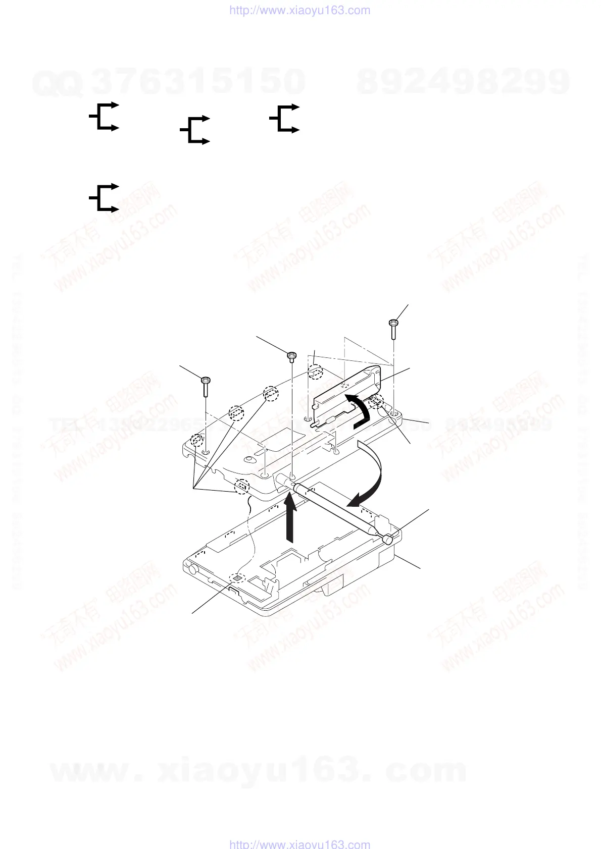
DISASSEMBLY
Note : Follow the disassembly procedure in the numerical order given.
3-1. CABINET (LOWER), CABINET ASSY
r
The equipment can be removed using the following procedure.
Cabinet (Lower) ASSY
Cabinet ASSY
Set
Chassis ASSY
Microcomputer board
Main board
Key board
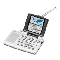
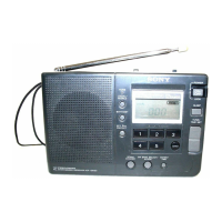
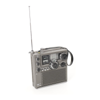
<RADIO SECTION>
Cabinet (Front), Reel ASSY
Cabinet (Rear), Reel board, Control board
Set
<ANTENNA CONTROLLER SECTION>
<RADIO SECTION>
3
Screws (+BTP 2x8)
4
Screw (M 1.7)
3
Screws (+BTP 2x8)
5
Claws
5
Claw
5
Claw
Lid, Battery case
Cabinet (lower) ASS
Antenna, Telescopic
Cabinet ASSY
1
6
2
7
Remove solder
w
w
w
.
x
i
a
o
y
u
1
6
3
.
c
o
m
Q
Q
3
7
6
3
1
5
1
5
0
9
9
2
8
9
4
2
9
8
T
E
L
1
3
9
4
2
2
9
6
5
1
3
9
9
2
8
9
4
2
9
8
0
5
1
5
1
3
6
7
3
Q
Q
TEL 13942296513 QQ 376315150 892498299
TEL 13942296513 QQ 376315150 892498299
http://www.xiaoyu163.com
http://www.xiaoyu163.com