– 30 –
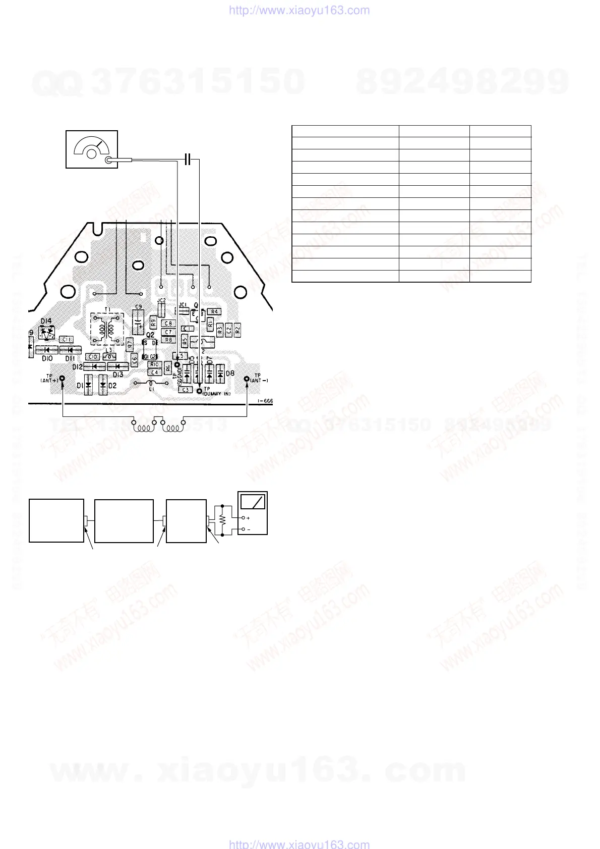
SW FREQUENCY Adjustment
BAND : AM
VOLUME control : as required
Connection Points :
Note : Disconnect a loop antenna ASSY from the antenna board,
and connect two dummy antenna coils in series connection.
ANTENNA
MDULE
(ANTENNA
BOARD)
ANTENNA
CONTROLLER
level mete
16
Ω
J1,J2
J101
(AM EXT ANT)
J302
(headphone)
SET
(MAIN
BOARD)
Procedure :
1. Align the set with the frequency of the AM RF signal generator
shown on the table below.
2. Align RV401 - RV412 for each band meter band until the high-
est reading is obtained on the level meter.
AM RF SSG frequency Meter band Adjust part
2.4MHz 120mb RV401
3.3MHz 90mb RV403
3.95MHz 75mb RV405
4.9MHz 60mb RV407
6.075MHz 49mb RV409
7.25MHz 41mb RV411
9.7MHz 31mb RV402
11.825MHz 25mb RV404
13.7MHz 22mb RV406
15.35MHz 19mb RV408
18.275MHz 16mb RV410
23.5MHz 13mb RV412
Caution :Always perform the SW Frequency Adjustment after hav-
ing replace the main circuit board or antenna circuit board.
Adjustments Location : MAIN board (see page 33)
AM RF SSG
TP
(SG GND)
Two dummy antenna coils 1
µ
H (1-410-497-11)
TP
(DUMMY IN)
30% amplitude modulation
by 400Hz signal.
Output level :
as low as possible
[ANTENNA BOARD]
(Side B)
0.5pF
w
w
w
.
x
i
a
o
y
u
1
6
3
.
c
o
m
Q
Q
3
7
6
3
1
5
1
5
0
9
9
2
8
9
4
2
9
8
T
E
L
1
3
9
4
2
2
9
6
5
1
3
9
9
2
8
9
4
2
9
8
0
5
1
5
1
3
6
7
3
Q
Q
TEL 13942296513 QQ 376315150 892498299
TEL 13942296513 QQ 376315150 892498299
http://www.xiaoyu163.com
http://www.xiaoyu163.com