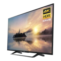
Do you have a question about the Sony KD-43X720E and is the answer not in the manual?
Details the history and versions of the service manual.
Identifies the placement of various circuit boards.
Exploded views, screws, connectors, and parts for the 43-inch model.
Detailed exploded view for the KD-43X7*E model disassembly.
Exploded views, screws, connectors, and parts for the 49-inch model.
Detailed exploded view for the KD-49X7*E model disassembly.
Exploded views, screws, connectors, and parts for the 55-inch model.
Detailed exploded view for the KD-55X7*E model disassembly.
Exploded views, screws, connectors, and parts for the 65-inch model.
Detailed exploded view for the KD-65X7*E model disassembly.
General servicing instructions and precautions for safe operation.
Cautions for handling the LCD panel safely during repair.
Precautions regarding the handling and replacement of lithium batteries.
Post-repair safety checks before releasing the TV to the customer.
Procedure for measuring AC leakage current to ensure electrical safety.
Methods to verify a proper earth ground connection for safety.
Information regarding the use of lead-free solder on circuit boards.
Proper techniques for inserting and removing flexible flat cables.
Interpreting LED blinking patterns for error diagnosis.
Diagnosing and resolving audio output issues based on blinking codes.
Troubleshooting steps for panel power related errors indicated by blinking.
Diagnosing issues related to I2C communication with the panel.
Troubleshooting steps for scenarios with a blank screen but visible backlight.
Diagnosing and resolving no picture problems related to the tuner.
Troubleshooting steps for failures in analog TV tuning.
Troubleshooting for digital tuning failures in specific regions.
Troubleshooting for digital tuning failures in other regions.
Diagnosing problems with the CI slot for conditional access modules.
Troubleshooting steps for when there is no picture via HDMI connection.
Diagnosing High-bandwidth Digital Content Protection (HDCP) related issues.
Troubleshooting +5V power failures affecting HDMI connectivity.
Troubleshooting +5V power failures affecting HDMI connectivity.
Diagnosing Hot Plug Detect (HPD) signal problems for HDMI.
Diagnosing Hot Plug Detect (HPD) signal problems for HDMI.
Troubleshooting I2C communication errors related to HDMI.
Diagnosing TMDS signal problems affecting HDMI performance.
Troubleshooting issues with HDMI CEC (Bravia Sync) functionality.
Diagnosing problems when HDMI ARC (Audio Return Channel) is not working.
Troubleshooting steps for WIFI search and connection failures.
Diagnosing no picture problems related to the analog video signal path.
Diagnosing no picture problems related to the analog video signal path.
Details normal operating conditions and parameters for the Audio D Amp IC.
Comprehensive guide to diagnosing and resolving various audio problems.
Troubleshooting steps for no sound from the main speakers.
Diagnosing and resolving no sound issues from the headphone jack.
Troubleshooting steps for no sound from analog audio inputs.
Diagnosing and resolving no sound issues related to analog RF signals.
Troubleshooting steps for no sound from HDMI audio inputs.
Diagnosing and resolving issues with HDMI ARC audio functionality.
Troubleshooting steps for no sound issues from USB audio playback.
Troubleshooting steps for no power issues related to DDCON/LDO circuits.
Step-by-step guide on how to access the TV's service menu.
List of service mode items whose availability depends on TV region.
Explains the function of remote control keys within the service menu.
Procedure to access and perform self-diagnosis checks from the service menu.
Details on interpreting diagnosis menu items, error codes, and operation times.
Table correlating LED flashing times with specific failure monitoring items.
How to verify and set Panel Selection and LVDS Spectrum values.
Instructions for editing the TV's serial number via the service menu.
Procedure for setting the model number, which can only be done once.
Steps for adjusting white balance settings after replacing main board or panel.
Process for transferring White Balance, Mura, and CUC data.
How to activate and operate the aging mode for testing.
Steps to perform tuner detection and verify its status.
How to disable ATMOS CEC to avoid conflicts with compliant devices.
How to set CEC Force LA to avoid conflicts with non-CEC devices.
Procedure to read HDMI EDID data without external equipment.
How to set shipping region and tuner ID options for service purposes.
Visual identification of circuit boards for 43-inch and 49-inch models.
High-level functional block diagrams illustrating system architecture.
Detailed diagrams showing connector pinouts for KC_43 and KC_49 models.
Detailed diagrams showing connector pinouts for KC_55 and KC_65 models.
| Screen Size | 43 inches |
|---|---|
| Resolution | 3840x2160 (4K UHD) |
| Display Technology | LCD |
| Smart TV | Yes |
| Operating System | Android TV |
| HDMI Ports | 3 |
| USB Ports | 2 |
| Wi-Fi | Yes |
| Refresh Rate | 60 Hz |
| Audio Output | 10W + 10W |
| Bluetooth | No |
| HDR | Yes |
