3-28
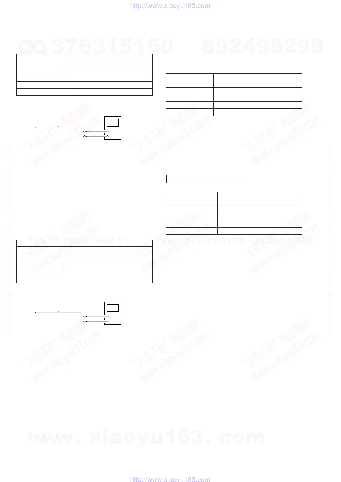
[VCOM R Adjustment]
Condition:
Input signal SVGA 60 Hz: RGB 0.7 Vp-p, 16 Step
Measurement point MA-324 (H) board CN206 pin qs
Measuring equipment Digital voltmeter
Adjustment page F
Adjustment address 75
Specification value 6.64 ± 0.02 V
Connection:
Adjustment Procedure:
(1) Connect a digital voltmeter to the CN206 pin qs on the MA-
324 (H) board.
(2) Set (or confirm) data: 01 to page: 0, address: 01.
(Cancel F page protect)
(3) On page: F, address: 75, change data with the PLAY and
STOP buttons and press the PAUSE button to write data so
that the digital voltmeter reading satisfies the specification
value.
Adjustment and Connection Location: MA-324 (H) board
(see page 3-30)
[VCOM L Adjustment]
Condition:
Input signal SVGA 60 Hz: RGB 0.7 Vp-p, 16 Step
Measurement point MA-324 (H) board CN206 pin qf
Measuring equipment Digital voltmeter
Adjustment page F
Adjustment address 76
Specification value 6.64 ± 0.02 V
Connection:
Adjustment Procedure:
(1) Connect a digital voltmeter to the CN206 pin qf on the MA-
324 (H) board.
(2) Set (or confirm) data: 01 to page: 0, address: 01.
(Cancel F page protect)
(3) On page: F, address: 76, change data with the PLAY and
STOP buttons and press the PAUSE button to write data so
that the digital voltmeter reading satisfies the specification
value.
Adjustment and Connection Location: MA-324 (H) board
(see page 3-30)
[White Balance Adjustment]
Preparation:
Set data: 1F to page: F, address: 7B.
Condition:
Input signal SVGA 60 Hz: White (50%)
Measurement point LCD screens
Measuring equipment Not use (Eye-measurement)
Adjustment page F
Adjustment address 6B, 6D
Specification value With no color
Adjustment Procedure:
(1) Set (or confirm) data: 01 to page: 0, address: 01.
(Cancel F page protect)
(2) Page: F, address: 6B, 6D
Change data at these two addresses with the PLAY and STOP
buttons and press the PAUSE button to write data so that the
LCD screens turn gray.
[Power Saving Sensor Adjustment]
Mode PC
Signal No signal
Measurement point Displayed data on the adjusting remote
Measurement equipment commander
Adjustment page F
Adjustment address 57
Adjustment Procedure:
(1) Place the reflector (a board pasted kent paper) 6.5 cm away
from sensor.
(2) Set (or confirm) data: 01 to page: 0, address: 01.
(Cancel F page protect)
(3) Set data: 08 to page: F, address 8C.
(Same condition when the POWER SAVE is set to ON)
(4) Set initial value data: 00h to page: F, address: 57.
(5) Set data: 03 to page: 0, address: FF.
(6) See data in page: 3, address: 12.
OK: More than 80.
NG: Below 7F.
If NG, repeat step (4) to (6) after add 08h to the initial value
data of setp (4).
(7) Set data: 00 to page: 0, address: FF.
(8) Set data: 02 to page: F, address: 8C.
Note: It is necessary to input data: 03 to page: 0, address: FF before read-
ing the data in page: 03. Also without input the data: 00 to page: 0,
address: FF, you cannot input any data to page: F after the data in
page: 3 is read.
MA-324 (H) Board
Digital Voltmeter
+
–
CN206 pin
qs
(COM R)
CN206 pin
9
(GND)
MA-324 (H) Board
Digital Voltmeter
+
–
CN206 pin
qf
(COM L)
CN206 pin
9
(GND)
POWER SAVING SENSOR
w
w
w
.
x
i
a
o
y
u
1
6
3
.
c
o
m
Q
Q
3
7
6
3
1
5
1
5
0
9
9
2
8
9
4
2
9
8
T
E
L
1
3
9
4
2
2
9
6
5
1
3
9
9
2
8
9
4
2
9
8
0
5
1
5
1
3
6
7
3
Q
Q
TEL 13942296513 QQ 376315150 892498299
TEL 13942296513 QQ 376315150 892498299
http://www.xiaoyu163.com
http://www.xiaoyu163.com