3-29
[Battery Down Adjustment]
Mode PC
RGB IN: No signal
Signal PC AUDIO IN: No signal
VOLUME: Minimum
Measurement point
Displayed data on adj. remote commander
Measuring equipment
Adjustment page F
Adjustment address 7E, 7F, 80, 81, 82, 83
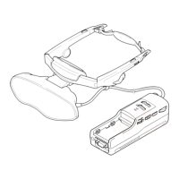
Connection:
Referring to Fig. 3-4 (see page 3-30), connect the following equip-
ment.
(1) Connect the regulated power supply and a digital voltmeter
to the battery terminal.
(2) Connect the adjusting remote commander to the CN501 on
MA-324 (H) board.
(3) Connect a PC to the RGB (J101) terminals.
Menu Setting:
• Picture and sound set standard. (see page 3-19)
Adjustment Procedure:
(1) Adjust the output voltage of regulated power supply so that
the battery terminals voltage is 6.0 ± 0.01 Vdc.
(2) Turn ON the POWER switch on the set.
(3) Set data: 01 to page: 0, address: 01.
(4) Set data: 03 to page: 0, address: FF.
(5) Set data: 0A to page: 2, address: 01.
(6) Read data (ZZh) on page: 3, address: 7D.
(7) Set data: 00 to page: 0, address: FF.
(8) Set data: 01 to page: 0, address: 01. (Cancel F page protect)
(9) Using the following formulas (calculation of hexadecimal
numbers), calculate the adjustment data and enter them to
respective adjustment addresses.
(Refer to 5. Data Processing on page 3-18)
Page: F Address: 7E F7E = ZZh
Page: F Address: 7F F7F = ZZh + 0Ah
Page: F Address: 80 F80 = ZZh + 0Dh
Page: F Address: 81 F81 = ZZh + 10h
Page: F Address: 82 F82 = ZZh + 16h
Page: F Address: 83 F83 = 01
(10) Set data: 00 to page: 0, address: 01.
Note: After setting each data, be sure to press the PAUSE button on the
adjusting remote commander.
[Charge Adjustment]
Mode PC
RGB IN: No signal
Signal PC AUDIO IN: No signal
VOLUME: Minimum
Measurement point
Displayed data on adj. remote commander
Measuring equipment
Adjustment page E, F
01, 02, 03, 04, 05 (E page)
Adjustment address
FE (F page)
Connection:
Referring to Fig. 3-4 (see page 3-30), connect the following equip-
ment.
(1) Connect the regulated power supply and a digital voltmeter
to DC IN 8.4 V jack (J701).
(2) Connect the adjusting remote commander to the CN501 on
MA-324 (H) board.
(3) Connect a PC to the RGB (J101) terminal.
Menu Setting:
Picture and sound set standard. (see page 3-19)
Adjustment Procedure:
(1) Adjust the output voltage of regulated power supply so that
DC IN 8.4 V jack (J701) voltage is 8.85 ± 0.01 Vdc.
(2) Turn ON the POWER switch on the set.
(3) Set data: 01 to page: 0, address: 01.
(4) Set data: 03 to page: 0, address: FF.
(5) Set data: 0A to page: 2, address: 01.
(6) Read data (XXh) on page: 3, address: 74.
(7) Set data: 00 to page: 0, address: FF.
(8) Set data: 01 to page: 0, address: 01. (Cancel E and F page
protect)
(9) Using the following formulas (calculation of hexadecimal
numbers), calculate the adjustment data and enter them to
respective adjustment addresses.
(Refer to 5. Data Processing on page 3-18)
Page: E Address: 01 E01 = XXh
Page: F Address: FE FFE = XXh – 39h
(10) Set data: 00 to page: 0, address: 01.
(11) Connect the regulated power supply and a digital voltmeter
to the battery terminals.
(12) Adjust the output voltage of regulated power supply so that
the battery terminal voltage is 8.35 ± 0.01 Vdc.
(13) Set data: 03 to page: 0, address: FF.
(14) Set data: 0A to page: 2, address: 01.
(15) Read data (YYh) on page: 3, address: 75.
(16) Set data: 00 to page: 0, address: FF.
(17) Set data: 01 to page: 0, address: 01.
(18) Using the following formulas (calculation of hexadecimal
numbers), calculate the adjustment data and enter them to
respective adjustment addresses.
(Refer to 5. Data Processing on page 3-18)
Page: E Address: 02 E02 = YYh
Page: E Address: 03 E03 = YYh – 02h
Page: E Address: 04 E04 = YYh – 55h
Page: E Address: 05 E05 = YYh + 02h
(19) Set data: 00 to page: 0, address: 01.
Note: After setting each data, be sure to press the PAUSE button on the
adjusting remote commander.
POWER SUPPLY BLOCK
w
w
w
.
x
i
a
o
y
u
1
6
3
.
c
o
m
Q
Q
3
7
6
3
1
5
1
5
0
9
9
2
8
9
4
2
9
8
T
E
L
1
3
9
4
2
2
9
6
5
1
3
9
9
2
8
9
4
2
9
8
0
5
1
5
1
3
6
7
3
Q
Q
TEL 13942296513 QQ 376315150 892498299
TEL 13942296513 QQ 376315150 892498299
http://www.xiaoyu163.com
http://www.xiaoyu163.com