EasyManuals Logo

Sony MHC-V5 Service Manual

Sony MHC-V5
102 pages
To Next Page IconTo Next Page
To Previous Page IconTo Previous Page
Page #5 background imageLoading...
Page #5 background image
MHC-V5
5
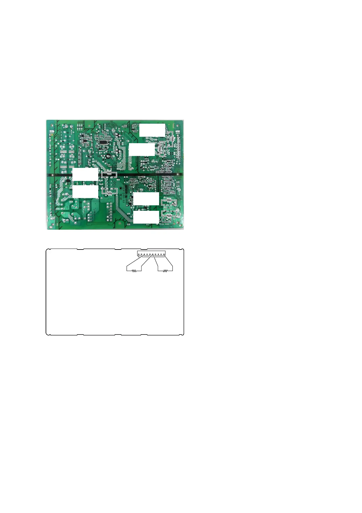
CAPACITOR ELECTRICAL DISCHARGE PROCESSING
When checking the board, the electrical discharge is necessary for
the electric shock prevention.
Connect the resistor to both ends of respective capacitors.
• D-AMP board
CN1000 (pin 6 and 10, pin 6 and 3)
Switching regurator (SWR1)
C202, C203, C403, C407, C531 and C532
– Switching Regurator (Conductor Side) –
– D-AMP Board (Conductor Side) –
800 :/2 W
(for C403)
800 :/2 W
(for C407)
800 :/2 W
(for C531)
800 :/2 W
(for C532)
800 :/2 W
(for C203)
800 :/2 W
(for C202)
800 :/2 W
(pin 3 and 6)
800 :/2 W
(pin 6 and 10)
110
CN1000

Table of Contents

Other manuals for Sony MHC-V5

Questions and Answers:

Question and Answer IconNeed help?

Do you have a question about the Sony MHC-V5 and is the answer not in the manual?

Sony MHC-V5 Specifications

General IconGeneral
On/off switchYes
Product colorBlack
Recommended usageUniversal
Suitable for outdoor use-
Speaker type3-way
Driver diameter250 mm
Speaker positionFront
Tweeter diameter40 mm
Number of drivers3
Speaker placementFloor
Audio output channels1.0 channels
Mid-range driver diameter100 mm
Number of tweeter drivers1
Recommended amplifier power (max)240 W
Recommended amplifier power (min)0.5 W
Impedance5 Ω
Frequency range- Hz
RMS rated power1440 W
Peak Music Power Output (PMPO)15840 W
Number of amplifier channels2 channels
Power source typeAC
USB 2.0 ports quantity2
Connectivity technologyWired & Wireless
AC input voltage120 V
AC input frequency60 Hz
TypeHome audio mini system
Weight and Dimensions IconWeight and Dimensions
Depth325 mm
Width339 mm
Height908 mm
Weight18000 g

Related product manuals