13
Connecting Devices
Connection
2
Connect the switcher processor and control panel.
a Connect the MVS connector of the switcher
processor and the MVS connector of the control
panel using a LAN cable.
3
Connect the control panel and menu panel.
a Connect the DVI-D connector of the control panel
and the DVI-D connector of the menu panel using
the DVI cable supplied with the menu panel.
b Connect the DEVICE 1 connector of the control
panel and the DEVICE connector on the bottom of
the menu panel using the USB cable supplied with
the menu panel.
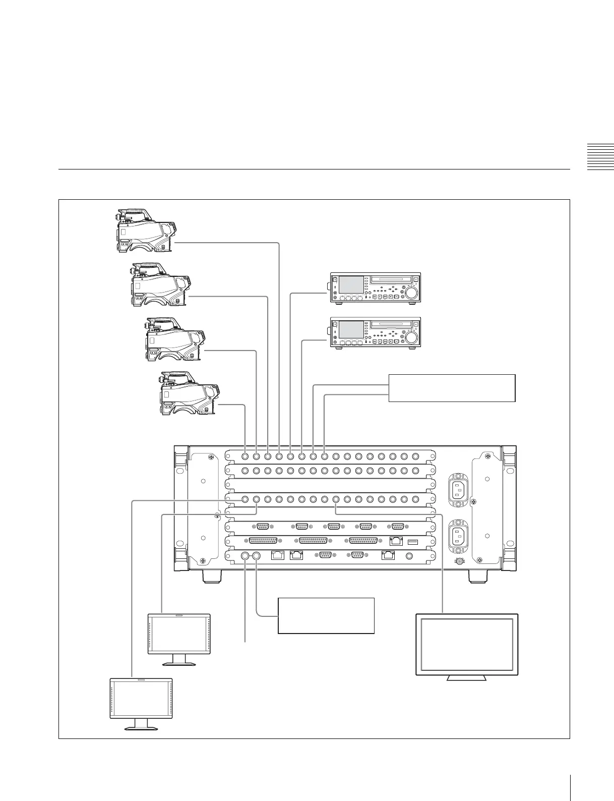
Peripheral Device Connection
O S
G
ME U
P GE D PL Y
UB
P
3
HFT
E U
E
M RK
T
H MB
L
T
L
K Y N I
E A D
C A ER
E W
PR V
N XTL Y S OP REC
H 1 H H CH
L AL
C E
L V L
R
P S
HO ES
OG
ME U
P E D Y
UB
LP
HFT
P
E U
E
M RK
ET
H MB
N IL
E ET
H T L
O
K I
E A D
C A ER
F E F W
D
PR V N XTL Y S OP
S AN B
REC
E E T
1 C
L AL
C E
L V L
R
P S
PRIMARY INPUTS 1 2 3 4 5 6 7 8
OUTPUTS 1
2
REF INPUT
REF INPUT OUTPUTS 9
Character generator
Reference signal
generator
75 ohm terminator
Video signal
Key signal