28
Setting Tally
Preparation
Setting Tally
Setting Parallel Tally
The red tallies for PRIMARY INPUTS 1 to 48 are
assigned to the TALLY connector on the switcher
processor by default.
For details about changing the assignment settings, refer
to the User’s Guide.
Setting Serial Tally
Set the red tally of the program output (P/P PGM1) and the
green tally of the preview output (P/P PVW) to be output
from the SERIAL TALLY connector of the switcher
processor.
This section describes the procedure when “P/P PGM1” is
assigned to the OUTPUTS 1 connector and “P/P PVW” is
assigned to the OUTPUTS 2 connector.
1
Set the position of the MVS system in S-Bus space.
Router menu
a Open the Engineering Setup >Router/Tally
>Router menu (7361).
b In the <Device> group, select the target device.
In this example, select [SWR1].
c In the <Matrix Size> group, select the matrix size.
In this example, select [136x138 (Standard)].
d Set each of the [Source], [Destination], and [Level]
parameters to “1”.
2
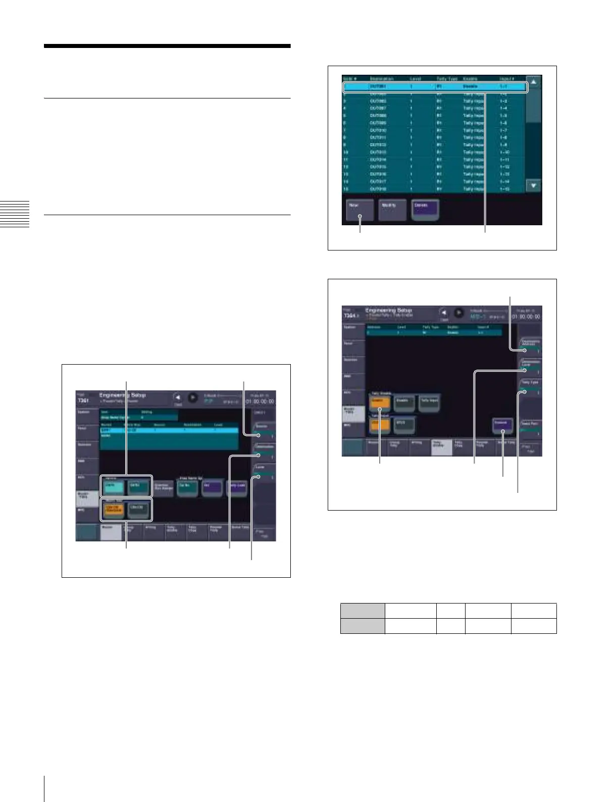
Set the tally generation reference.
Tally Enable menu
New menu
a Open the Engineering Setup >Router/Tally >Tally
Enable menu (7364).
b Check the tally settings for the program output.
If the settings of “OUT001” are as follows, you do
not need to change the settings. Proceed to step g.
c Press [New].
The New menu (7364.1) appears.
d Set each of the [Destination Address], [Destination
Level], and [Tally Type] parameters to “1”.
e In the <Tally Enable> group, select [Enable].
f Press [Execute].
Matrix Size Destination
Source
Level
Device
Setting Destination Level Tally Type Enable
Value OUT001 1 R1 Enable
New Tally settings for program output
Enable
Destination Address
Destination Level
Execute
Tally Type