40
Setting the Startup State
Preparation
b In the <Setup> or <Initial Status> group, select
[User].
For details about settings for the startup state when
power is applied, see “Customizing the User
Default Settings” (1 p. 40).
Factory default settings
a In the <Start Up Mode> group, select [Custom].
b In the <Setup> or <Initial Status> group, select
[Factory].
[Resume] can be set only when switcher processor or
control panel is selected.
4
Repeat steps 2 and 3 as required to set other devices.
5
Apply and save the settings.
a Press [Execute].
b Check the message, then press [Yes].
Customizing the User Default
Settings
User default settings are one option for startup mode when
power is turned on.
There are two user default settings available, stored in
flash memory in the switcher processor.
•Setup
• Initial Status
The data saved as “Setup” is data relating to menus other
than the Engineering Setup >System menu.
The data saved as “Initial Status” is data relating to the
state of each device, excluding the “Setup” settings.
For details about the data that is saved, refer to the User’s
Guide.
You can customize and save user default settings to recall
the same operation state when power is turned on. Or you
can recall saved user settings to return to a known state if
an error occurs. Data settings can also be saved as a backup
on USB flash memory or other removable disks.
When shipped, the contents of user default settings in flash
memory is the same as the [Factory] settings.
1
Set the state you want to save as a user default settings.
2
Display the menu.
a Open the Engineering Setup >System >Start Up
menu (7314).
3
Select the target device to save.
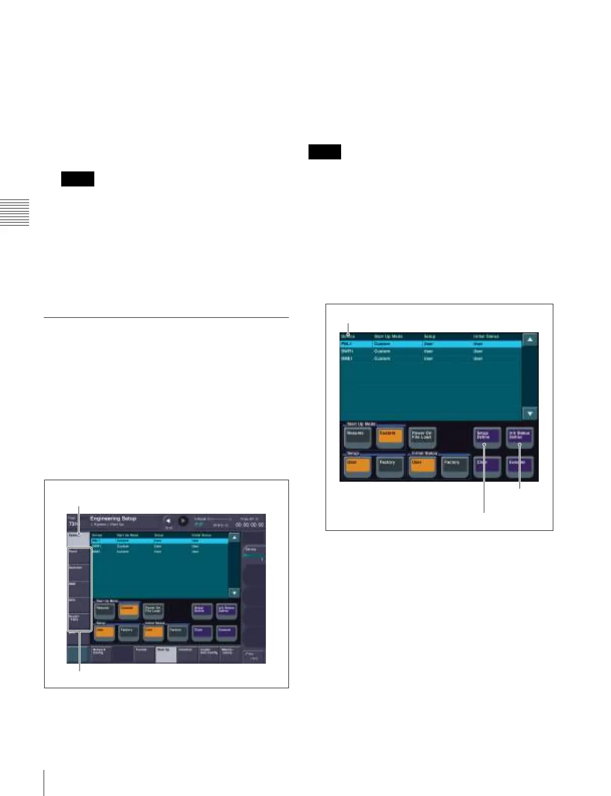
Start Up menu
a Select switcher processor (SWR), control panel
(PNL), or DME in the [Device] column.
4
Save customized data.
To save “Setup” data
a Press [Setup Define].
b Check the message, then press [Yes].
To save “Initial Status” data
a Press [Init Status Define].
b Check the message, then press [Yes].
5
Repeat steps 1 to 4 as required to set other devices.
Notes
Settings in the System menu and
submenus are not saved.
Settings in these menus are saved.
Notes
Setup Define
Init Status
Define
Device