Power Supply and Connectors 57
Chapter
2
Names
and
Functions
of
Parts
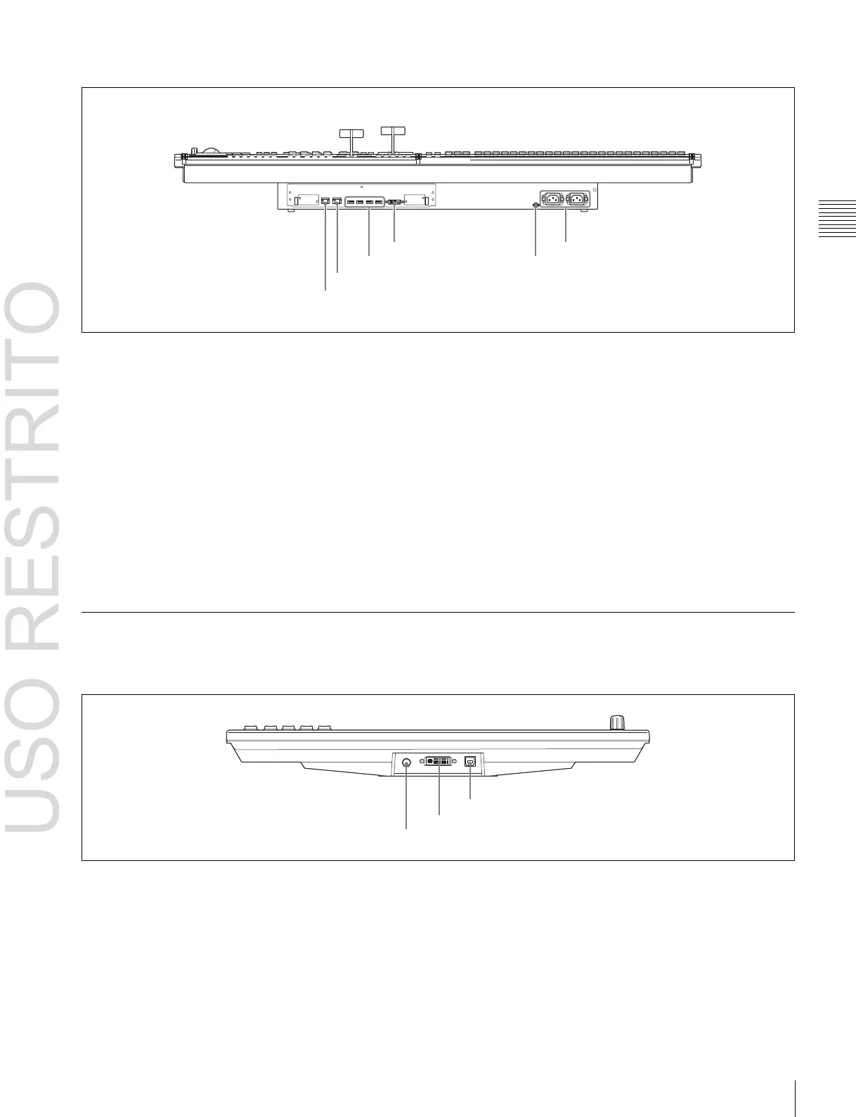
Rear panel
d
DVI-D connector
f
-
AC
IN A and B connectors
c
DEVICE 1 to 4 connectors
e
U
terminal
b
MVS connector
a
UTIL connector
ICP-6520 diagram shown.
a
UTIL (utility) connector (RJ-45 compliant)
Intended for future expansion.
b
MVS (multi format video switcher) connector (RJ-
45 compliant)
Connect to the MVS-6520/6530/3000A/3000 multi format
switcher processor. Connect to an Ethernet switch
1)
if
connecting a DCU, MVE-8000A/9000 multi format DME
processor, and other devices.
c
DEVICE 1 to 4 connectors (USB 2.0 compliant,
USB Type-A)
Connect to an ICP-6511 menu panel or a USB device.
1)
d
DVI-D connector
Connect to an ICP-6511 menu panel or external monitor.
1)
e
U (signal ground) terminal
Connect to the system ground.
f
-
AC IN (AC power input) A and B connectors
(3-pin)
Connect to 100 V to 240 V AC power supply with the
optional AC power cords.
The unit is equipped with two power supplies. When A or
B power supply is connected, unit operation can proceed.
1) For information about devices that can be connected, contact your Sony
representative.
ICP-6511 Menu Panel
Bottom panel
c
DEVICE connector
b
DVI-D connector
a
DC IN connector
a
DC IN connector
Connect to the 12V DC connector of the supplied AC
adaptor.
b
DVI-D connector
Connect to the DVI-D output of the ICP-series control
panel.
c
DEVICE connector (USB 2.0, USB Type-B)
Connect to the DEVICE 1 connector of the ICP-series
control panel.