31
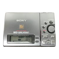
MZ-B10
8. Press the [SPEED CONTROL +] key to set the address value
to the next address for adjustment.
•Keys available when the cursor is on the address value
[DISPLAY] key on the remote commander: address value + 1000(h)
[P MODE] key on the remote commander: address value + 0100(h)
[SOUND] key on the remote commander: address value - 0100(h)
key on the remote commander: address value + 0010(h)
[SPEED CONTROL +] key: adjusted value + 0001(h)
[SPEED CONTROL
-
] key: adjusted value - 0001(h)
x key: moving the cursor to the adjusted value
9. Press the x key to move the cursor to the adjusted value.
10. While referring to the patch data list repeat the data correction
write procedure from step 6 to 9 until the address 2B98 is com-
pleted (until writing the last value at step 7).
11. Press the
[TRACK MARK] key or press the [DISPLAY] key
of the remote commander for several seconds to exit the RAM
monitor.
adjusted value
(blinking : cursor)
2A15**
023
Set LCD display
address value
adjusted value
(blinking : cursor)
2A15**
023
Set LCD display
address value
adjusted value
2B9800
023
Set LCD display (writing is complete to the address 2B98
12. Press the X key or press the key on the remote com-
mander to write all patch data to the nonvolatile memory.
13. Turn off the power.
 Loading...