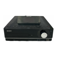
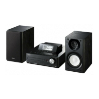
NAS-E35HD/SS-CE35HD
64
USB MICOM BOARD IC2 D708E001BRFP266 (USB SYSTEM CONTROLLER)
Pin No. Pin Name I/O Description
1 VSS - Ground terminal
2, 3
EM_A (_18),
EM_A (_13)
O Address signal output to the fl ash memory
4 CD-PO O Power supply on/off control signal output terminal for the CD section "H": power on
5 MCK - Not used
6 VSS - Ground terminal
7 EM_A (_19) O Address signal output to the fl ash memory
8 CVDD - Power supply terminal (+1.2V)
9 BCKI I Bit clock signal input from the data buffer
10 DVDD - Power supply terminal (+3.3V)
11 D_RESET O
Reset signal output to the data buffer, A/D converter, D/A converter,
USB interface and USB 2.0 hub controller "L": reset
12 LRCKI I L/R sampling clock signal input from the data buffer
13 VSS - Ground terminal
14 XRESET I Reset signal input from the system controller "L": reset
15 VSS - Ground terminal
16 CVDD - Power supply terminal (+1.2V)
17 CLKIN I System clock (22.5792MHz) input terminal
18 VSS - Ground terminal
19 TMS - Not used
20 CVDD - Power supply terminal (+1.2V)
21 XTRST - Not used
22 OSCVSS - Ground terminal
23 OSCIN - Not used
24 OSCOUT - Not used
25 OSCVDD - Power supply terminal (+1.2V)
26 VSS - Ground terminal
27 PLLHV - Power supply terminal (+3.3V)
28 TDI - Not used
29 TDO - Not used
30 VSS - Ground terminal
31 DVDD - Power supply terminal (+3.3V)
32 EMU (0) - Not used
33 CVDD - Power supply terminal (+1.2V)
34 EMU (1) - Not used
35 TCK - Not used
36 VSS - Ground terminal
37 EM_CAS O Column address strobe signal output to the SDRAM
38 EM_WE O Write enable signal output to the SDRAM, fl ash memory and USB interface
39 EM_WE_DQM (0) O Write enable signal output to the SDRAM
40 VSS - Ground terminal
41 EM_D (7) I/O Two-way data bus with the SDRAM, fl ash memory and USB interface
42 DVDD - Power supply terminal (+3.3V)
43 EM_D (6) I/O Two-way data bus with the SDRAM, fl ash memory and USB interface
44 CVDD - Power supply terminal (+1.2V)
45, 46 EM_D (5), EM_D (4) I/O Two-way data bus with the SDRAM, fl ash memory and USB interface
47 VSS - Ground terminal
48, 49 EM_D (3), EM_D (2) I/O Two-way data bus with the SDRAM, fl ash memory and USB interface
50 DVDD - Power supply terminal (+3.3V)
51, 52 EM_D (1), EM_D (0) I/O Two-way data bus with the SDRAM, fl ash memory and USB interface
53 CVDD - Power supply terminal (+1.2V)
54 VSS - Ground terminal
55, 56 EM_D (15), EM_D (14) I/O Two-way data bus with the SDRAM, fl ash memory and USB interface
57 CVDD - Power supply terminal (+1.2V)
58, 59 EM_D (13), EM_D (12) I/O Two-way data bus with the SDRAM, fl ash memory and USB interface
60 DVDD - Power supply terminal (+3.3V)
61 EM_D (11) I/O Two-way data bus with the SDRAM, fl ash memory and USB interface
62 VSS - Ground terminal
• IC Pin Function Description