6-1
1
2
A001
3
not supplied
3
main chassis block
5
#2
(Tightening torque:
6.0
±
0.5kgf-cm)
#2
(Tightening torque:
6.0
±
0.5kgf-cm)
4
BDP-S500
NOTE:
• -XX and -X mean standardized parts, so they may
have some difference from the original one.
• Color Indication of Appearance Parts
Example:
KNOB, BALANCE (WHITE) . . . (RED)
↑↑
Parts Color Cabinet's Color
• Items marked “*” are not stocked since they are
seldom required for routine service. Some delay
should be anticipated when ordering these items.
• The mechanical parts with no reference number in
the exploded views are not supplied.
• Accessories and packing materials are given in the
last of the electrical parts list.
•Abbreviation
AUS: Australian model
CND : Canadian model
RUS: Russian model
SECTION 6
REPAIR PARTS LIST
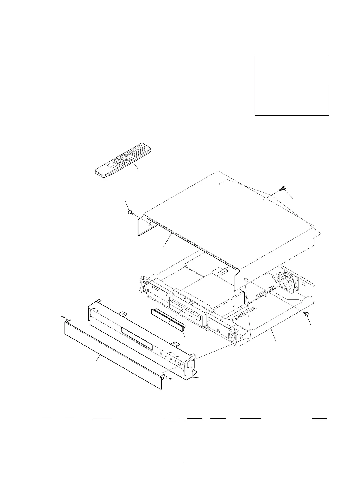
6-1. EXPLODED VIEWS
6-1-1. CASE ASSY
Ref. No. Part No. Description Remark
Ref. No. Part No. Description Remark
1 X-2178-990-1 FRONT PANEL ASSY (EXCEPT UK)
1 X-2187-783-1 FRONT PANEL ASSY (UK)
2 X-2178-991-1 COVER TRAY ASSY
3 3-070-883-71 SCREW, TAPPING
4 A-1436-998-A DISPLAY FRONT BLOCK (SERVICE)
5 A-1436-999-A CASE BLOCK (SERVICE USE SOEM)
A001 1-479-848-31 REMOTE COMMANDER (RMT-B101A)
(US, CND)
A001 1-480-207-21 REMOTE COMMANDER (RMT-B101P)
(AEP, UK, RUS, AUS)
#2 7-682-145-01 SCREW +P 3X4 (Tightening torque:
6.0±0.5kgf-cm)
Les composants identifiés par une
marque 0 sont critiquens pour la
sécurité.
Ne les remplacer que par une pièce
portant le numéro spécifié.
The components identified by mark
0 or dotted line with mark 0 are
critical for safety.
Replace only with part number
specified.
 Loading...