HT-CT780
8
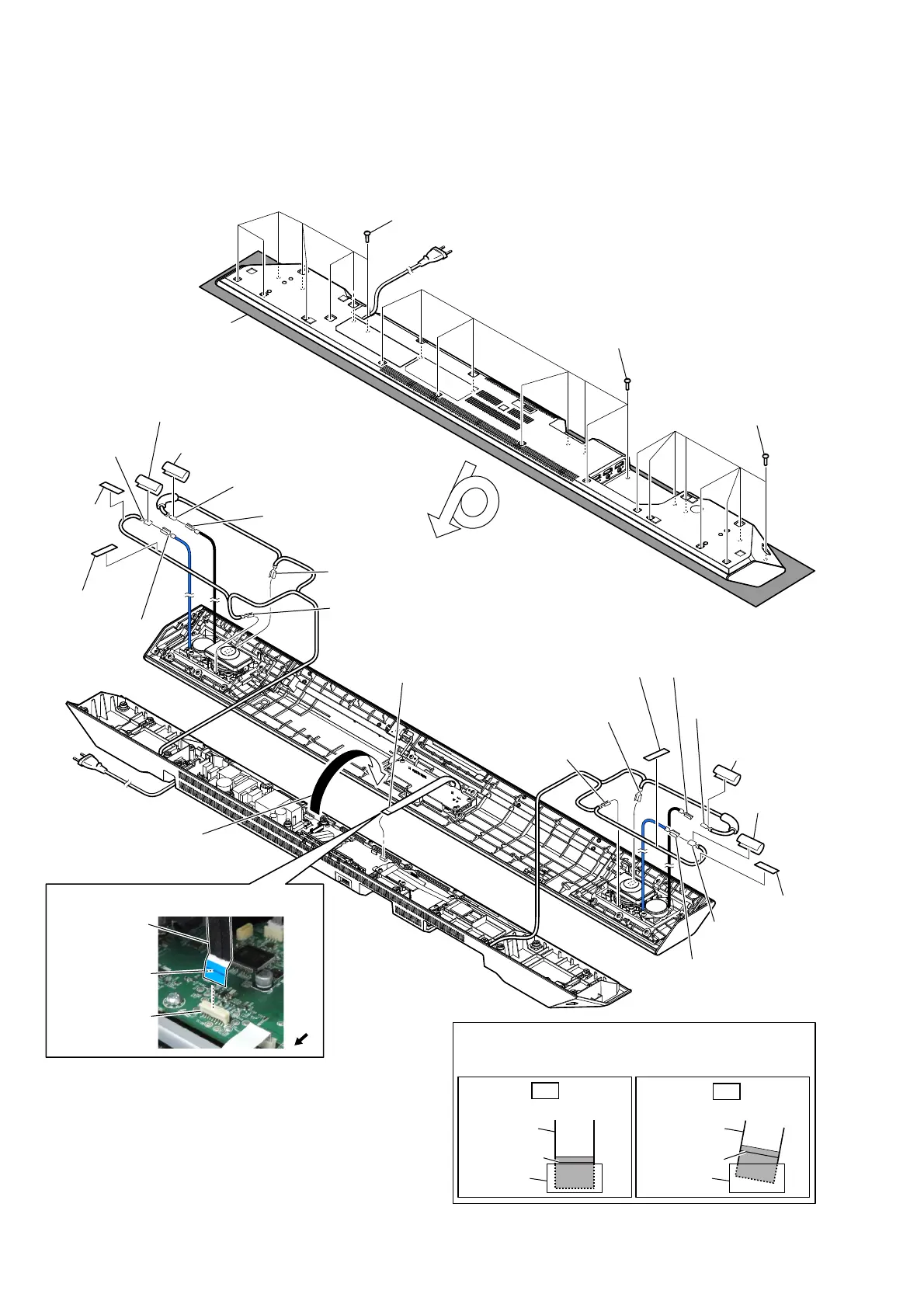
Note: Follow the disassembly procedure in the numerical order given.
2-2. TOP PANEL BLOCK
• For the speaker cable setting, see page 9.
7 terminal [gray]
(wide side)
6 terminal [black]
(wide side)
6 terminal [gray]
(narrow side)
6 terminal [black]
(narrow side)
6 terminal [blue]
(wide side)
7 terminal [black]
(narrow side)
4 cushion (CZ)
5 cushion top
5 cushion top
4 cushion (CZ)
5 cushion top
5 cushion top
6 terminal [black]
(narrow side)
6 terminal [blue]
(wide side)
6 terminal
[black]
(wide side)
6 terminal [red]
(narrow side)
7 terminal [red]
(wide side)
7 terminal [black]
(narrow side)
4 cushion (CZ)
4 cushion
(CZ)
2 Remove the top panel
block in the direction
of the arrow.
1 eight screws
(BVTP3 u 10)
1 nine screws
(BVTP3 u 10)
1 eight screws
(BVTP3 u 10)
– Bottom view –
– Rear view –
3 flexible flat cable
(18 core) (FFC3)
(CN104)
colored line
Insert straight into the interior.
flexible flat
cable
connector
OK
colored line
Insert at a slant.
flexible flat
cable
connector
NG
How to install the flexible flat cable
When installing the flexible flat cable, ensure that
the colored line is parallel to the connector after insertion.
Note:
Please spread a sheet under a
unit not to injure top panel.
)OH[LEOHIODWFDEOH))&VHWWLQJ
flexible flat cable
(18 core) (FFC3)
connector
(CN104)
Terminal face is
below side.
front
side