2-14
BVM-A14
[G2 Adjustment]
n
These adjustment menus are located in the SYSTEM
CONFIGURATION menu → MAINTENANCE →
DEFLECTION (4/5).
1. Input the 1080/60i (1125) color bar signal to the
BKM-68X (analog component input adaptor). (CHRO-
MA: OFF state)
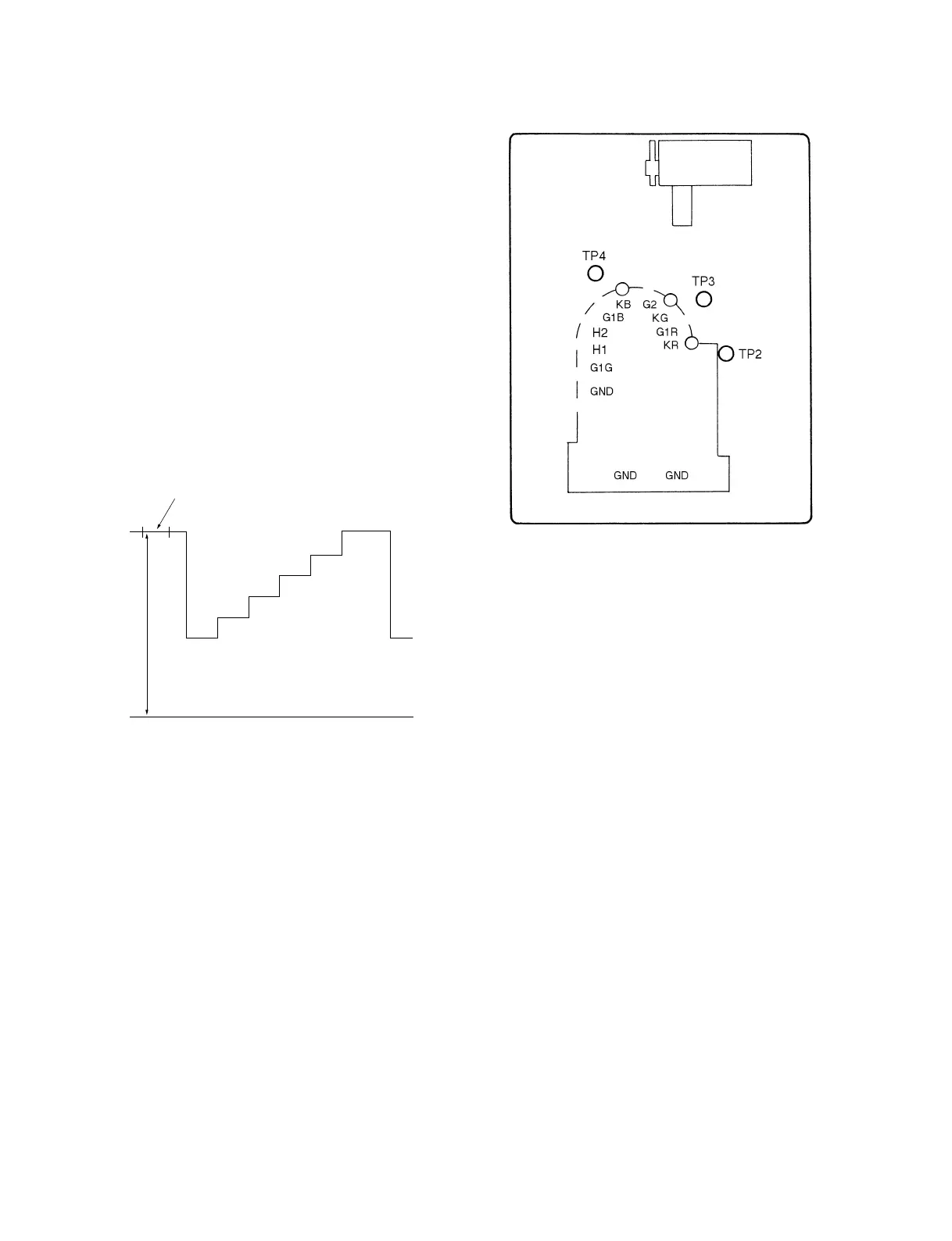
2. Connect the probe of the oscilloscope to each R, G, B
cathode (TP2, 3, 4) of the C board, and check the DC
voltages of the color bar signal pedestal portions.
(20 V/Div)
3. Connect the probe of the oscilloscope to the cathode
with the highest pedestal DC voltage.
4. Adjust the G2 REF data so that the DC voltage at the
pedestal becomes the value as shown below.
Specifications : 100 ± 2.5 Vdc
Fig. 1-21
Pedestal
DC
0V
C board -B SIDE-
Fig. 1-22