4-4
BVM-A14
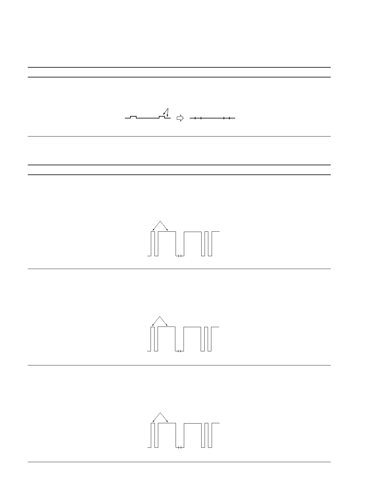
Procedure
1. Bright center adjustment
Adjustment Operation Standard Adjusting Point
. Connect the oscilloscope to TP602. The TP602 waveform is flat: The adjustment menu is
Level difference: 0 ± 4 mV BRIGHT CENTER
in SYSTEM CONFIGURATION →
MAINTENANCE → VIDEO (2/5).
2. 100 IRE adjustment
Adjustment Operation Standard Adjusting Point
Step 1
. Input “093” with the numeric keypad 100% WHITE level and the 100 IRE pulse level output The adjustment menu is
on the controller, and input the built-in from TP121 are equal: R 100 IRE
100% FLAT FIELD signal. Level difference: 0 ± 4 mV in SYSTEM CONFIGURATION →
. Connect the oscilloscope to TP121. MAINTENANCE → VIDEO (3/5).
Step 2
. Connect the oscilloscope to TP321. 100% WHITE level and the 100 IRE pulse level output The adjustment menu is
from TP321 are equal: G 100 IRE
Level difference: 0 ± 4 mV in SYSTEM CONFIGURATION →
MAINTENANCE → VIDEO (3/5).
Step 3
. Connect the oscilloscope to TP521. 100% WHITE level and the 100 IRE pulse level output The adjustment menu is
from TP521 are equal: B 100 IRE
Level difference: 0 ± 4 mV in SYSTEM CONFIGURATION →
MAINTENANCE → VIDEO (3/5).
Make it flat.
Make them equal.
Make them equal.
Make them equal.