34
KV-20FS120/21FM120/21FS120/21FA310/24FS120/25FS120
KV-20FS120/21FM120/21FS120/21FA310/24FS120/25FS120
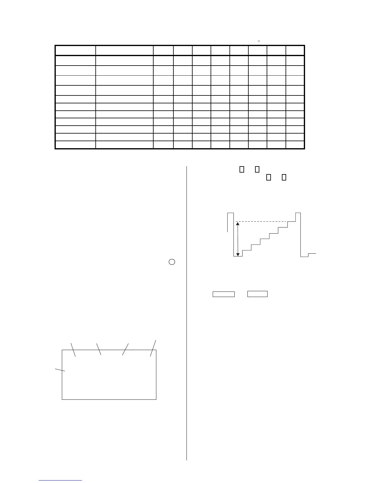
4-5. ID MAP TABLE
Model Destination ID-O ID-1 ID-2 ID-3 ID-4 ID-5 ID-6 ID-7
KV-20FS120
US
89 7 9340160 5
KV-20FS120
CND
89 7 9500160 5
KV-21FM120
L NORTH
81 3 0 130 32 16 48 69
KV-21FS120
L NORTH
81 7 9 130 32 16 48 69
KV-21FS120
L SOUTH
81 7 9 130 32 16 48 69
KV-21FA310
L NORTH
81 23 113 130 32 16 48 69
KV-21FA310
L SOUTH
81 23 113 130 32 16 48 69
KV-24FS120
US
89239340160 5
KV-24FS120
CND
89239500160 5
KV-25FS120
L NORTH
81 23 9 130 32 16 48 69
KV-25FS120
L SOUTH
81 23 9 130 32 16 48 69
5. Select SCON with
1
and
4
.
6. Adjust the value of SCON with
3
and
6
for 86 ± 3Vpp for 20/21 inch,
and 96 ± 3Vpp for 24/25 inch.
82 – 3Vpp for 24/25 inch
76 – 3Vpp for 20/21 inch
R ON: ON (1)
G ON: ON (1)
B ON: ON (1)
7. Press
MUTING
then
ENTER
to save into the memory.
4-6. A BOARD ADJUSTMENTS
H. Frequency (Free Run) Check
1. Input a TV mode (RF) with no signal.
2. Connect a frequency counter to base of Q502
(TP-25 H. DRIVE) on the A Board.
3. Check H. Frequency for 15735 ± 200 Hz.
V. Frequency (Free Run) Check
1. Select video 1 with no signal input.
2. Set the conditions for a standard setting.
3. Connect the frequency counter to TP-27 (V OUT) or CN515 pin
6
(V DY+) and ground on the A Board .
4. Check that V. Frequency shows 60 ± 4 Hz.
Drive (SCON)
1. Input a color-bar signal and set the level to 75%.
2. Set in Pro mode + PICTURE MAX.
3. Activate the Service Adjustment Mode.
service video rdrv
ntsc
vchp
Category
Display
Item
Mode
Item
Data
Signal
Type
00000000 00000000
26
R ON: ON (1)
G ON: OFF (0)
B ON: OFF (0)
4. Connect an oscilloscope probe to CV Board,
J1751Pin 12 (KR) (Red Out) .