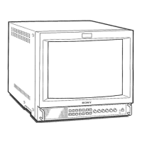
Location and Function of Parts and Controls
24
p LINE B button and lamp
Press this button to monitor the signal input through the
LINE B connectors.
q RGB/COMPONENT button and lamp
Press this button to monitor the signal input through the
RGB/COMPONENT connectors.
r OPTION 1 button and lamp
This button works when an optional board has been
installed in the option slot on the rear panel. Press this
button to monitor the video signal input through input 1
of the optional board and the audio signal input through
the OPTION AUDIO INPUT 1 jack.
s OPTION 2 button and lamp
This button works when an optional board has been
installed in the option slot on the rear panel. Press this
button to monitor the video signal input through input 2
of the optional board and the audio signal input through
the OPTION AUDIO INPUT 2 jack.
t Tally lamp
Lights up when a video camera connected to this
monitor is selected. For the tally lamp to function
properly, certain cabling is required.
For details on this cabling, see page 31.
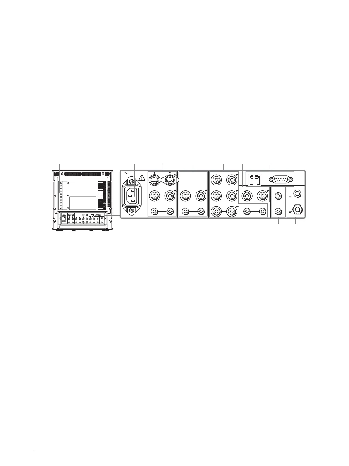
Rear Panel
a OPTION slot (BKM-129X)
If you install another option board, remove the BKM-
129X and then reinsert it.
RGB/COMPONENT IN connectors/EXT SYNC
(external synch) IN/OUT connectors
These are the input and output connectors for analog
RGB or component (Y, P
B
, P
R
) signals. You can monitor
them using the OPTION 1 button on the control panel.
For audio, use the OPTION AUDIO INPUT connectors.
When you use an external synchronization signal, set
RGB/EXT or COMP/EXT from RGB SYSTEM on the
USER CONFIG (1/2) menu.
You can install one optional board in this option slot. If
you install two boards, they do not function.
For details on how to install a board, refer to the
installation manual supplied with the optional board.
b AC IN socket
Connect the supplied AC power cord to this socket and
then to a wall outlet.
c LINE A connectors
Line input connectors for Y/C separate, composite video
and audio signals and their loop-through output
connectors.
Press the LINE A button on the control panel to monitor
the input signal through these connectors.
If you input signals to both Y/C IN and VIDEO IN, the
signal input to the Y/C IN is selected.
Y/C IN/OUT (4-pin mini-DIN)
These are the input/output connectors for a Y/C
separate signal. Connect them to the Y/C separate
input/output connectors on equipment such as a VCR,
video camera, or another monitor.
VIDEO IN/OUT (BNC)
These are the input/output connectors for a composite
video signal. Connect them to the composite video
input/output connectors on equipment such as a VCR,
video camera, or another monitor.
AUDIO IN/OUT (phono jack)
These are the input/output jacks for an audio signal.
Connect them to the audio input/output jacks on
equipment such as a VCR.
AC IN LINE A LINE B
VIDEO
AUDIO
IN OUT
IN
OUT
VIDEO
AUDIO AUDIO
PARALLEL RS-232C
OPTION
AUDIO INPUT
RGB/COMPONENT
IN OUT
IN
OUT
B/PB
G/Y
R/P
R
IN OUT
IN OUT IN
OUT
EXT
SYNC
IN OUT
1
2
REMOTE
89