39
OFF: Select when not using an external microphone.
PLUG-IN PWR: Select wh
en using an plug-in power
type microphone.
MONO BMP+5V: Sele
ct when using a Sony lavalier
microphone.
Adjusting the input level (INPUT LEVEL)
You can set the input level in the range –12 dB to +12 dB.
Adjust according to the microphone to be connected.
The factory default setting is 0 dB.
Setting the low-cut filter (LCF)
You can set the low-cut filter to reduce noise caused by
wind.
You can set the cutoff freq
uency to OFF/LOW/MID/
HIGH.
OFF: No filtering
LOW: 10
0 Hz cutoff frequency
MID: 15
0 Hz cutoff frequency
HIGH: 20
0 Hz cutoff frequency
Switching the phase of the microphone
(PHASE)
You can switch the phase of a connected microphone to
output audio in reverse phase.
NORMAL: Phase is not reversed.
INVERT: R
everses the phase internally.
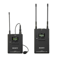
Selecting the connector for output of
input audio (OUTPUT ASSIGN)
Selects the connector for output of the input signal.
OUT1: Ou
tput audio from the OUTPUT 1 connector. If
the connected microphone is a stereo (L/R) type, the
signals are mixed for output.
OUT1/2 (L/R): Output audio from both the OUTPUT 1/
2 connectors. If the connected microphone is a stereo (L/
R) type, the L signal is output from OUTPUT 1 and the R
signal is output from OUTPUT 2.
OUT2: Ou
tput audio from the OUTPUT 2 connector. If
the connected microphone is a stereo (L/R) type, the
signals are mixed for output.
The following combination of output connector settings
are s
upported.
Parentheses ( ) indicate the output for ster
eo (L/R) type
microphones.
Transmitter Settings
Menu structure and operation
Procedure for all transmitters (UTX-B40/M40/
P40)
There are three menu display modes that can be selected
a
ccording to the application.
Simple mode
This mode displays only the required settings for
transmitting audio.
You can enable simple mode by setting MENU MODE
(menu
display mode) to SIMPLE.
Configuration menus
• GP/CH (group/channel) select
• BAND (frequency band) select
(Not available on the
Japan model, Korea model, 90U model, and E model)
• ATTENUATOR (attenuator) setting
• GAIN MODE (audio gain) setting
• LCF (low-cut filter) setting
• INPUT LEVEL (audio input level) se
lect (UTX-B40/
P40 only)
• RF POWER (RF transmit output level) select
• +48V SUPPLY (+48 V power supply) setting
(UTX
-P40 only)
• POWER LOCK (POWER bu
tton lock) function
• RUNNING TIME (accumulated running time) display
• MENU MODE (menu display mode) setting
The following configuration menus cannot be modified
du
ring transmission. Set these menus in transmission
stopped mode.
• GP/CH (group/channel) select
• BAND (frequency band) select
(Not available on the
Japan model, Korea model, 90U model, and E model)
• RF POWER (RF transmit output level) select
Advanced mode
This mode displays all configuration menus.
You can enable advanced mode by setting MENU MODE
(menu display mode) to ADV
ANCED.
The existing settings configured in advanced mode are
a
ctive even when using simple mode.
Configuration menus
• GP/CH (group/channel) select
• BAND (frequency band) select
(Not available on the
Japan model, Korea model, 90U model, and E model)
• ATTENUATOR (attenuator) setting
• GAIN MODE (audio gain) setting
• LCF (low-cut filter) setting
• INPUT LEVEL (audio input level) se
lect (UTX-B40/
P40 only)
MIC INPUT
OUTPUT1
OUTPUT2
OUT1
OUT2
(L)
(R)
(L+R)
(L+R)
OUT1/2 (L/R)
Note
Note