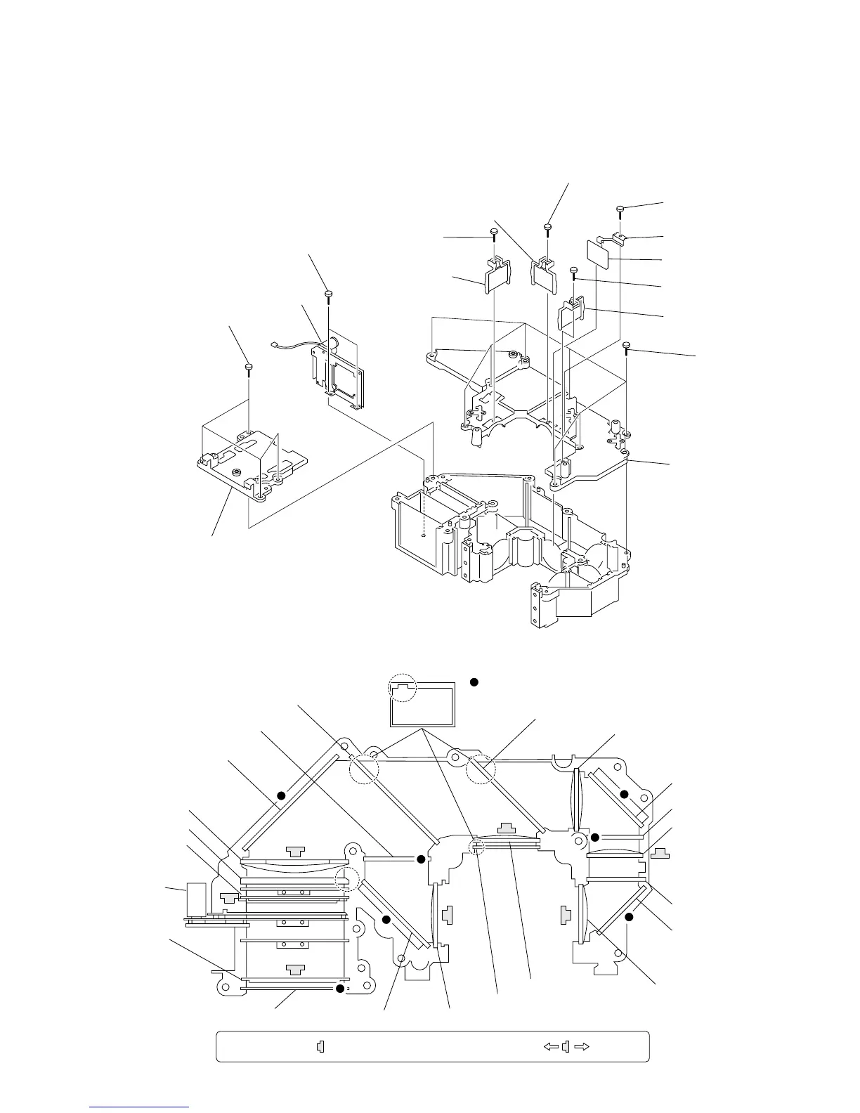
1-9
VPL-HS20
!] Two screws
(+BSW M2 x 5)
8 Screw
(+BSW M2 x 5)
9 In-polarizer panel
(R) assembly
3 Screw
(+BSW M2 x 5)
5 Screw
(+BSW M2 x 5)
7 G-trimming filter
1 Screw
(+BSW M2 x 5)
2 In-polarizer panel (B)
assembly
4 In-polarizer panel
(G) assembly
0 Eight screws
(+PTPW 3 x 10)
!- Unit cover (A)
![ Unit cover (BF)
!\ Iris unit
!= Four screws
(+PTPW 3 x 10)
6 G filter holder
1-3-11. Iris Unit and In-Polarizer panel (R), (G), (B) assembly
. Remove the C board. (Refer to 1-3-4.)
. Remove the opt block assembly. (Refer to 1-3-8.)
. Remove the opt unit assembly. (Refer to 1-3-9.)
B-CH condenser lens
G-trimming filter
GR-CH condenser lens
Note: Marked with indicates as shown below. Flat sideProjection side
Marking side
Marking side
B-channel mirror
R-channel mirror
G-reflect dichroic mirror
R-reflect dichroic mirror
R-trimming filter
Main mirror
Main condenser lens
P/S converter
Lens-2 flyeye
Iris unit
Lens-1 flyeye
Relay-1 lens
B-channel mirror
B-trimming filter
UV-cut filter
UVIR-cut filter
Relay-2 lens
1-3-12. Each Part Direction of Opt Unit Assembly