1-2
VPL-HS60/HS51A
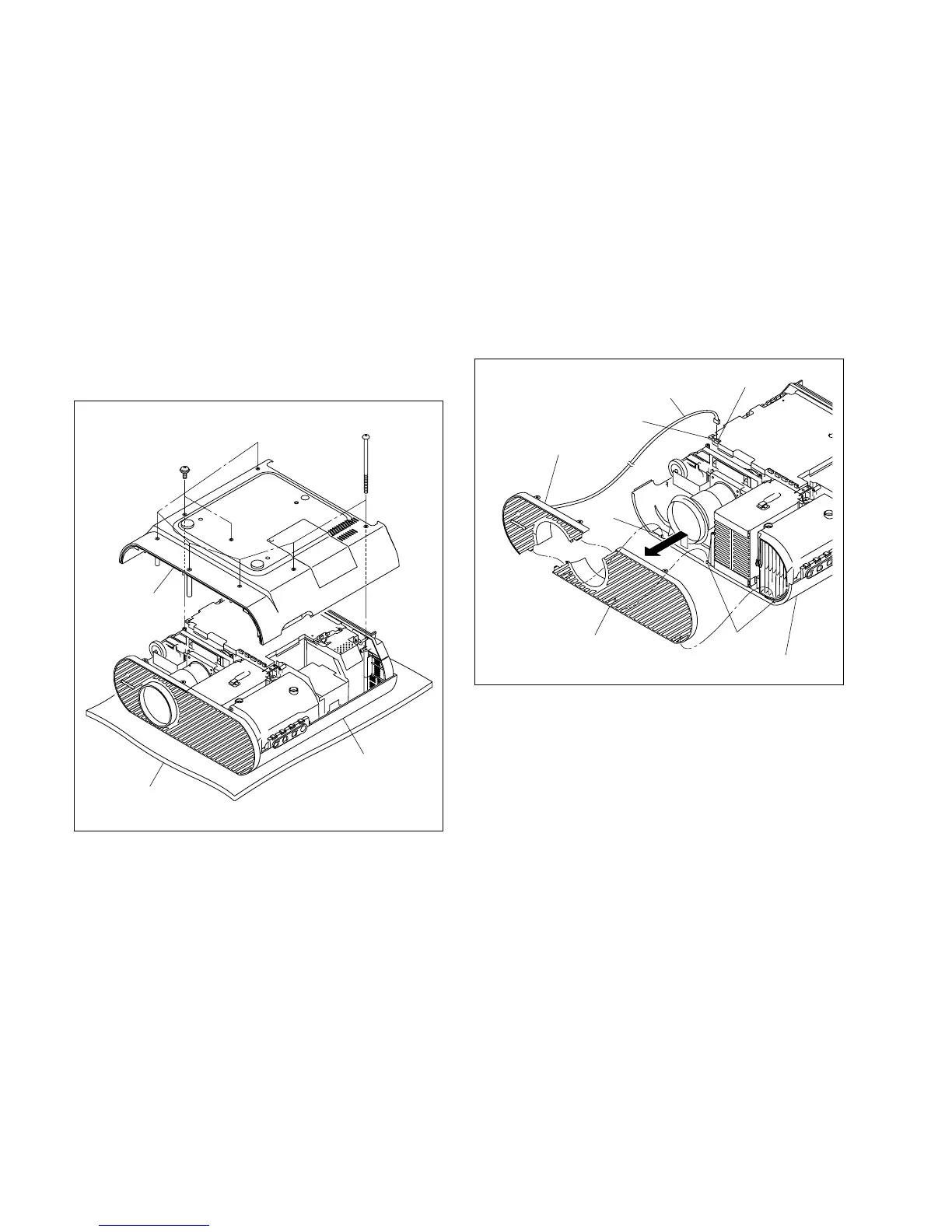
Top panel assembly
Conductive cushion
Base assembly
BV3 x 70
PSW3 x 8
1-3. Removing/Installing the Cabinet
n
When removing/installing or replacing the parts, place the
unit on the conductive cushion with the top panel assembly
down.
1-3-1. Base Assembly
Removal
1. Remove the six special screws (BV3 x 70) and two
screws (PSW3 x 8), then remove the base assembly.
Installation
2. Attach the base assembly.
1-3-2. Front Panel (D) Assembly/Front Panel
(U) Assembly
Removal (VPL-HS60)
1. Remove the base assembly. (Refer to Section 1-3-1.)
2. Disconnect the harness from the connector (CN1903)
on the C board, then remove the front panel (D).
3. Remove the front panel (U) assembly from the three
projections of the top panel assembly in the direction
shown by the arrow.
Installation (VPL-HS60)
4. Attach the front panel (D) assembly and front panel
(U) assembly in the reverse order of steps 2 and 3.
5. Attach the base assembly.
Front panel (D) assembly
C board
Projections
Projection
Front panel (U) assembly
To