1-3
VPL-HS60/HS51A
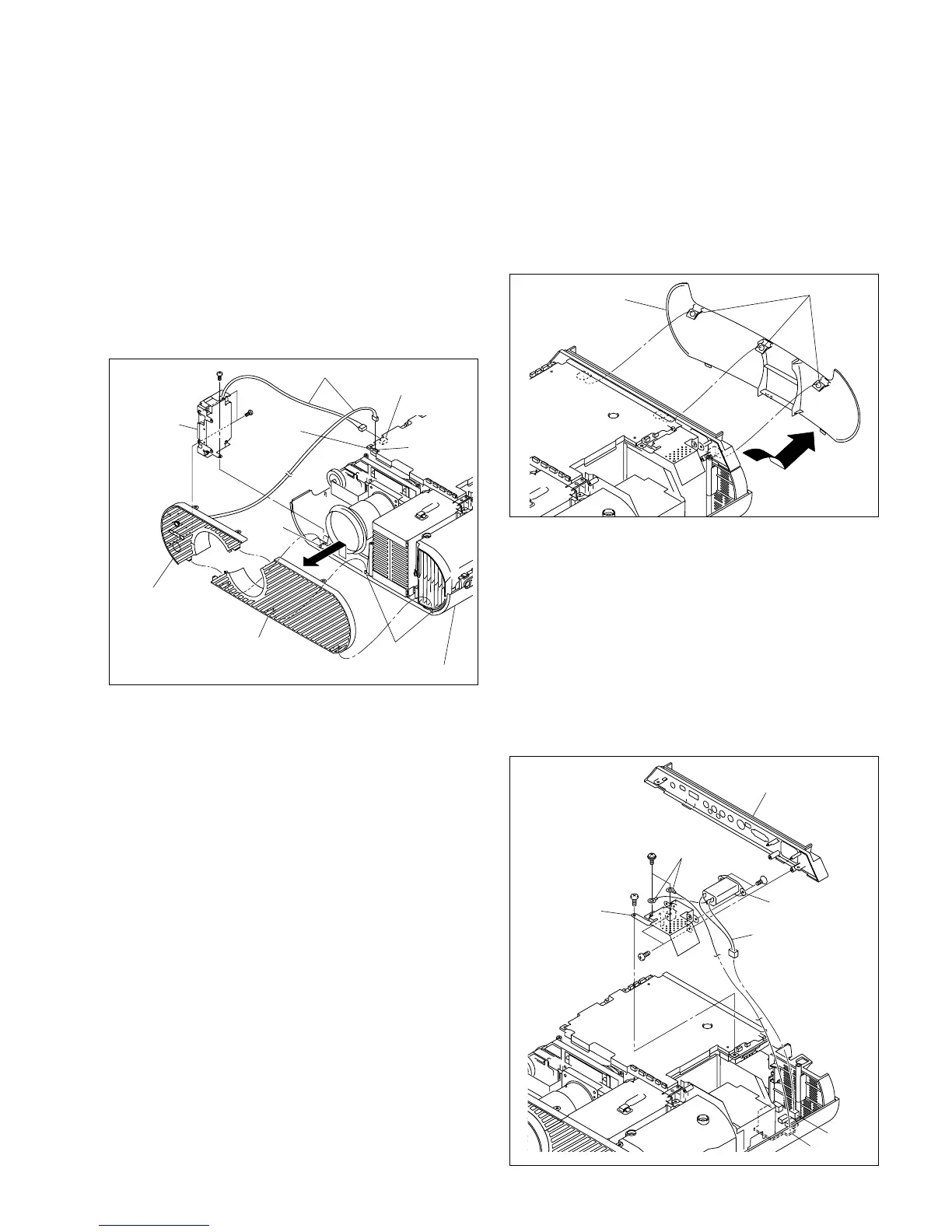
Removal (VPL-HS51A)
1. Remove the base assembly. (Refer to Section 1-3-1.)
2. Remove the screw and disconnect the two harnesses
from the connector (CN1806, 1903) on the C board,
then remove the front panel (D).
3. Remove the two screws, them remove the Q board
assembly.
4. Remove the front panel (U) assembly from the three
projections of the top panel assembly in the direction
shown by the arrow.
Installation (VPL-HS51A)
5. Attach the front panel (D) assembly and front panel
(U) assembly in the reverse order of steps 2 to 4.
6. Attach the base assembly.
BTP
3 x 12
BTP
3 x 12
Q board
assembly
C board
Harnesses
Front panel (D)
assembly
Front panel (U)
assembly
Projections
Projection
Top panel assembly
CN1903
CN1806
1-3-3. Rear Cover/Rear Panel
Removal
1. Remove the base assembly. (Refer to Section 1-3-1.)
2. Push the three portions A of the rear cover, then remove
the rear cover in the direction shown by the arrow.
3. Remove the screw (BTP3 x 12), then remove the
connector panel assembly.
4. Disconnect the harness from the connector (CN11) on
the F board.
5. Remove the two screws (BTP3 x 12), then remove the
bracket (AC).
6. Remove the two screws (PSW4 x 8), then disconnect
the two harnesses (GND) from the bracket (AC).
7. Remove the two screws (K3 x 6), then remove the AC
inlet.
 Loading...