2
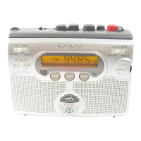
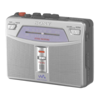
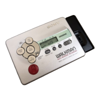
WM-GX410
TABLE OF CONTENTS
Flexible Circuit Board Repairing
• Keep the temperature of the soldering iron around 270°C
during repairing.
• Do not touch the soldering iron on the same conductor of the
circuit board (within 3 times).
• Be careful not to apply force on the conductor when soldering
or unsoldering.
Notes on chip component replacement
• Never reuse a disconnected chip component.
• Notice that the minus side of a tantalum capacitor may be
damaged by heat.
SECTION 1
GENERAL
This section is extracted
from instruction manual.
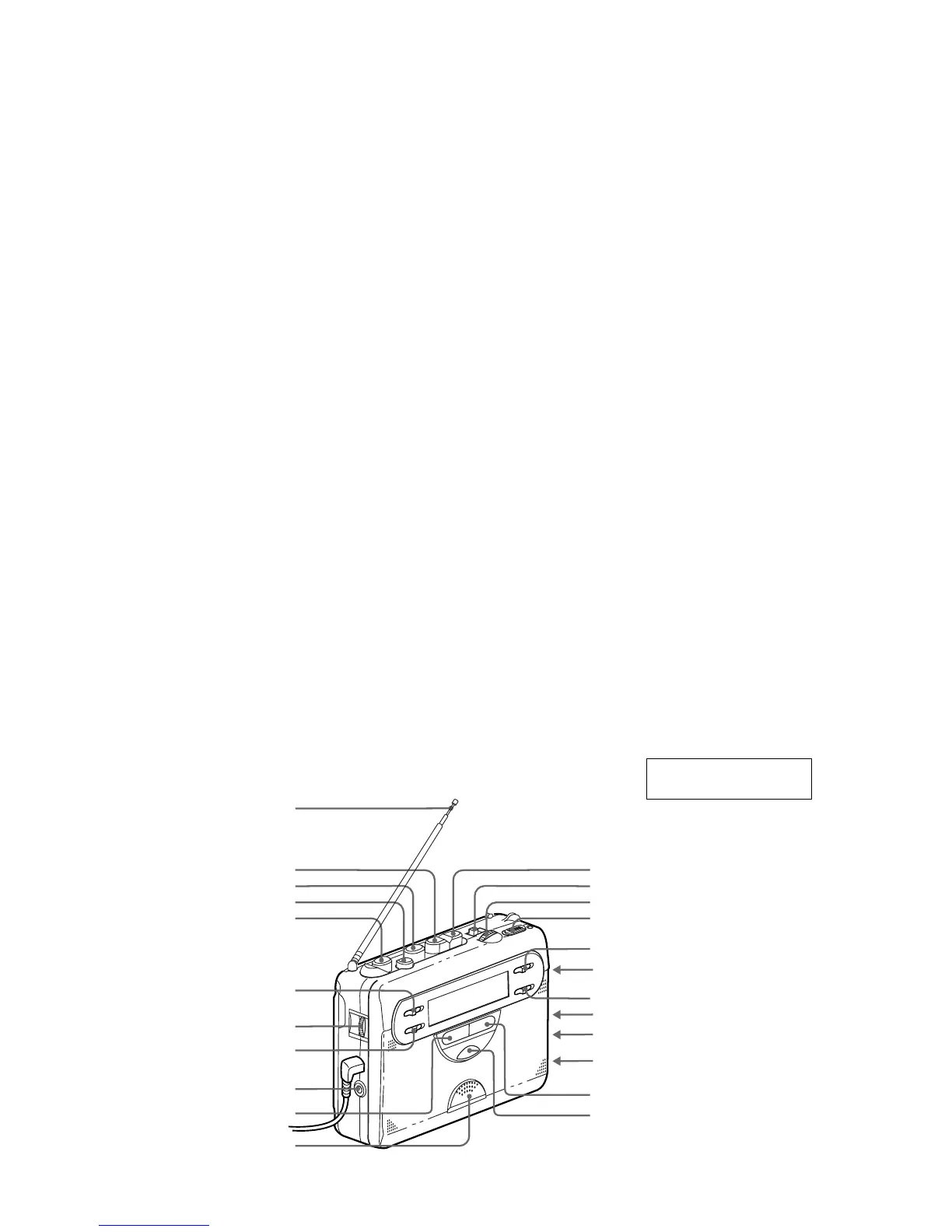
PAUSE
REC
DIR
REC TIME/PLAY MODE
AVLS
ISS
DC IN 3V
STOP
FF/CUEREW/REVIEW
PLAY**
VOL*
FM
AM
TUNE MODE
TUNING/ENTER
FM MODE•MONO/ST
FM MODE•LOCAL/DX
MIC (PLUG IN POWER)**
* There is a tactile dot beside VOL on the main unit to show the direction to turn
up the volume.
** The button or jack has a tactile dot.
Antenna
HOLD
Flat Mic
RADIO OFF
SOUND BOOST
Specifications ............................................................................ 1
1. GENERAL
Location of Parts and Controls ........................................ 2
2. DISASSEMBLY
2-1. Disassembly Flow .................................................... 3
2-2. Cabinet (Center), cabinet Front Assy ....................... 3
2-3. Main Board .............................................................. 4
2-4. Mechanism Deck (MT-WMFX410-175) ................. 4
2-5. Cassette Holder Sub Assy ........................................ 5
2-6. Sub Board................................................................. 5
2-7. Rec/PB/ Erase head (HRPE301), Belt (AR),
Capstan/Reel Motor (M601) ................................... 6
3. ADJUSTMENTS
3-1. Mechanical Adjustments .......................................... 7
3-2. Electrical Adjustments ............................................. 7
4. DIAGRAMS
4-1.IC Pin Function Descriptions .................................... 10
4-2. Block Diagrams –Tape Section– .............................. 11
4-3. Block Diagrams –Tuner Section– ............................ 12
4-4. Printed Wiring Board –Main Section (Side A)– ...... 13
Printed Wiring Board –Main Section (Side B)–....... 14
4-5. Schematic Diagram –Main Section (1/2)– ............... 15
4-6. Schematic Diagram –Main Section (2/2)– ............... 16
4-7. Printed Wiring Board –Sub Section (Side A)–......... 17
4-8. Printed Wiring Board –Sub Section (Side B)–......... 18
4-9. Schematic Diagram –Sub Section– .......................... 19
4-10.IC Block Diagrams.................................................. 20
5. EXPLODED VIEWS
5-1. Cabinet (Rear) Section ............................................. 22
5-2. Cassette Lid Section ................................................. 23
5-3. Mechanism Section-1 (MT-WMGX410-175).......... 24
5-4. Mechanism Section-2 (MT-WMGX410-175).......... 25
6. ELECTRICAL PARTS LIST .................................. 26
 Loading...