3
WM-GX410
SECTION 2
DISASSEMBLY
Note: Follow the disassembly procedure in the numerical order given.
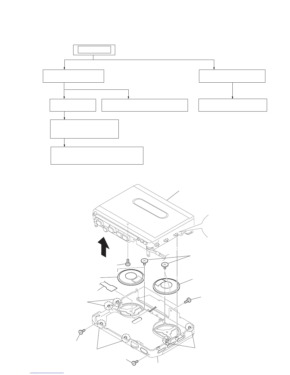
2-2. CABINET (CENTER), CABINET FRONT ASSY
• This set can be disassembled in the order shown below.
2-1. DISASSEMBLY FLOW
2-2. CABINET FRONT ASSY
(Page 3)
2-3. MAIN BOARD
(Page 4)
SET
2-2. CABINET (CENTER)
(Page 3)
2-4. MECHANISM DECK
(MT-WMFX410-175)
(Page 4)
2-5. CASSETTE HOLDER SUB ASSY
(Page 5)
2-7. REC/PB/ERASE HEAD (HRPE301),
BELT (AR), CAPSTAN/REEL MOTOR
(M601) (Page 6)
2-6. SUB BOARD
(Page 5)
1
two screws
2
screw (M1.4)
2
screw (M1.4)
5
two claws
7
fiexible board (CN301)
8
screw (M1.4 toothed lock)
3
two claws
4
two claws
SP402
SP401
cabinet front assy
9
four screws (tapping B2.0)
cabinet (center)
Align three switches and
three knobs
Note on installation
6

 Loading...