65
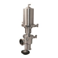
4. Install the microswitch bracket onto the
cylinder using the two microswitch bracket
screws and their washers. The screws require
a 5/32” hex wrench. Ensure to align the center
hole in the bracket so that it is concentric with
the actuator stem as shown in Fig. 13.
FIG. 13 - MICROSWITCH
BRACKET INSTALLATION.
MICROSWITCH ASSEMBLY INSTRUCTIONS
SP10MS/SP10PRX/SP20MS/SP20PRX
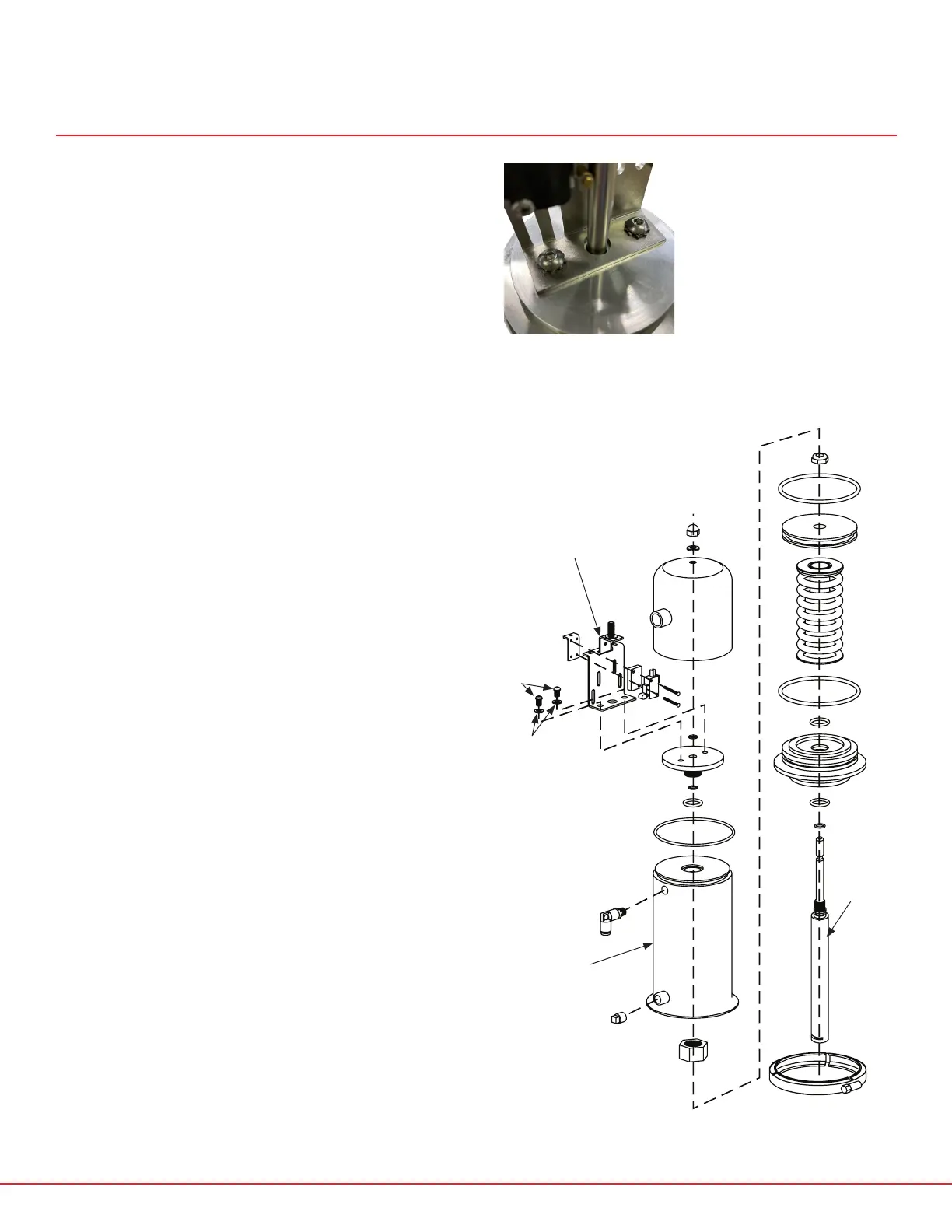
FIG. 14 - SP10MS/SP10PRX/SP20MS/SP20PRX ACTUATOR DIAGRAM
CYLINDER
SP10MS-1
MICROSWITCH
BRACKET
SP10MS-3
MICROSWITCH
BRACKET
SCREWS (X2)
SP10MS-3L
MICROSWITCH
WASHERS (X2)
SP10MS-3K
ACTUATOR
STEM
SP10MS-2D
 Loading...