64
MICROSWITCH ASSEMBLY INSTRUCTIONS
SP10MS/SP10PRX/SP20MS/SP20PRX
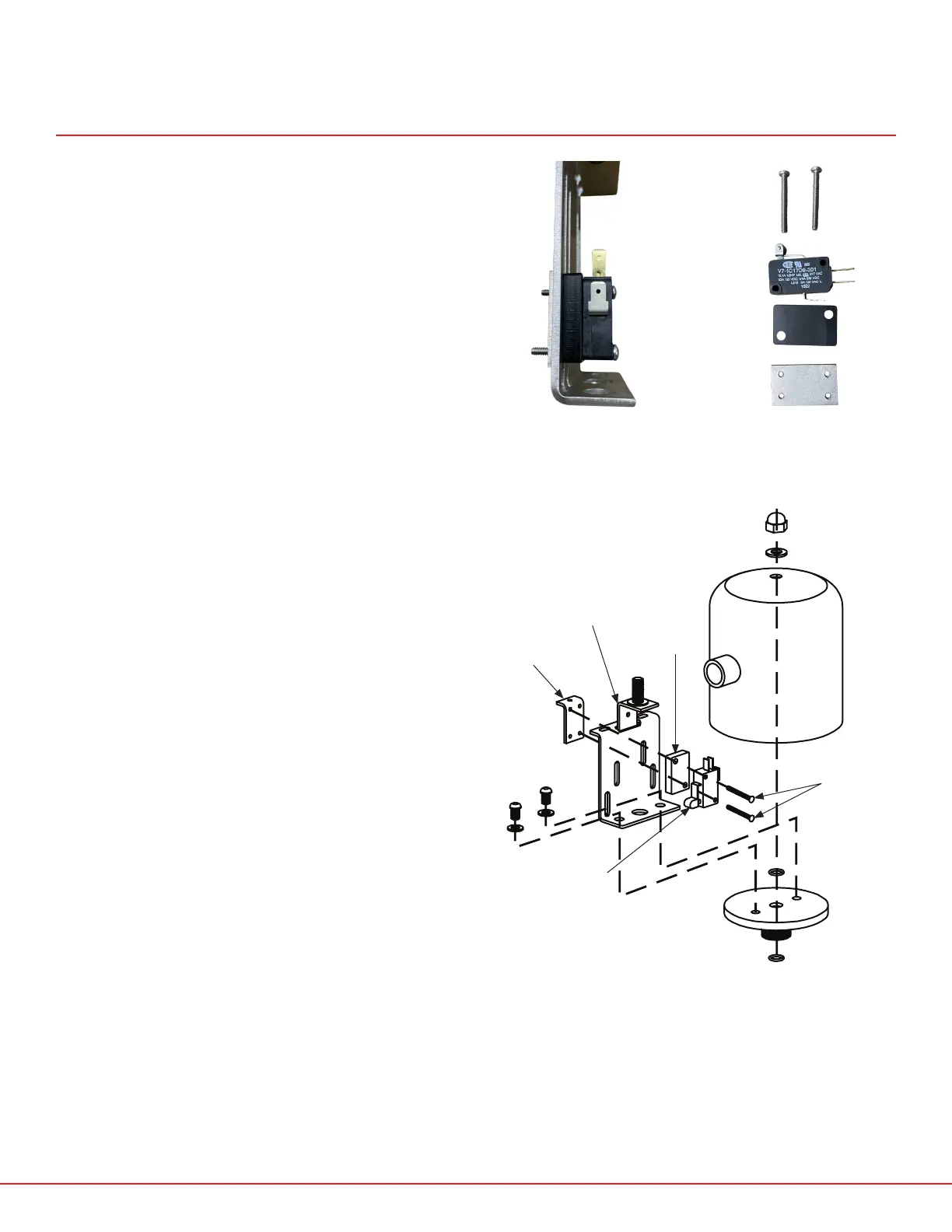
FIG.12 - SP10MS/SP10PRX/SP20MS/SP20PRX ACTUATOR DIAGRAM
MICROSWITCH
SP10MS-3B
MICROSWITCH
SCREWS (X2)
SP10MS-3C
MICROSWITCH
MOUNTING
BLOCK
SP10MS-3A
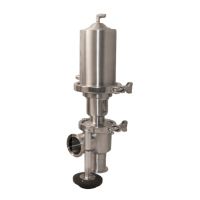
FIG. 10 - SIDE VIEW OF
INSTALLED MICROSWITCH
Figures 10 and 11 show the order in which
the installation of the microswitches, screws,
microswitch mounting blocks, and microswitch
adjusting bracket happens (see fig. 12). The
mounting block spaces the microswitches into
the center of the actuator stem and the adjusting
bracket acts as a nut and sandwiches the
microswitches to the microswitch bracket. Do not
install the lower microswitch too low, as this will
make installation more dicult, and it will need to
be adjusted in a future step anyway.
FIG. 11 - PARTS AND HARDWARE
IN ORDER
MICROSWITCH
ADJUSTING
BRACKET
SP10MS-3D
MICROSWITCH
BRACKET
SP10MS-3
 Loading...