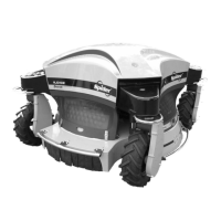
Operator Manual - Spider ILD02 SG
36 / 51 rev. 01-01-04-2011
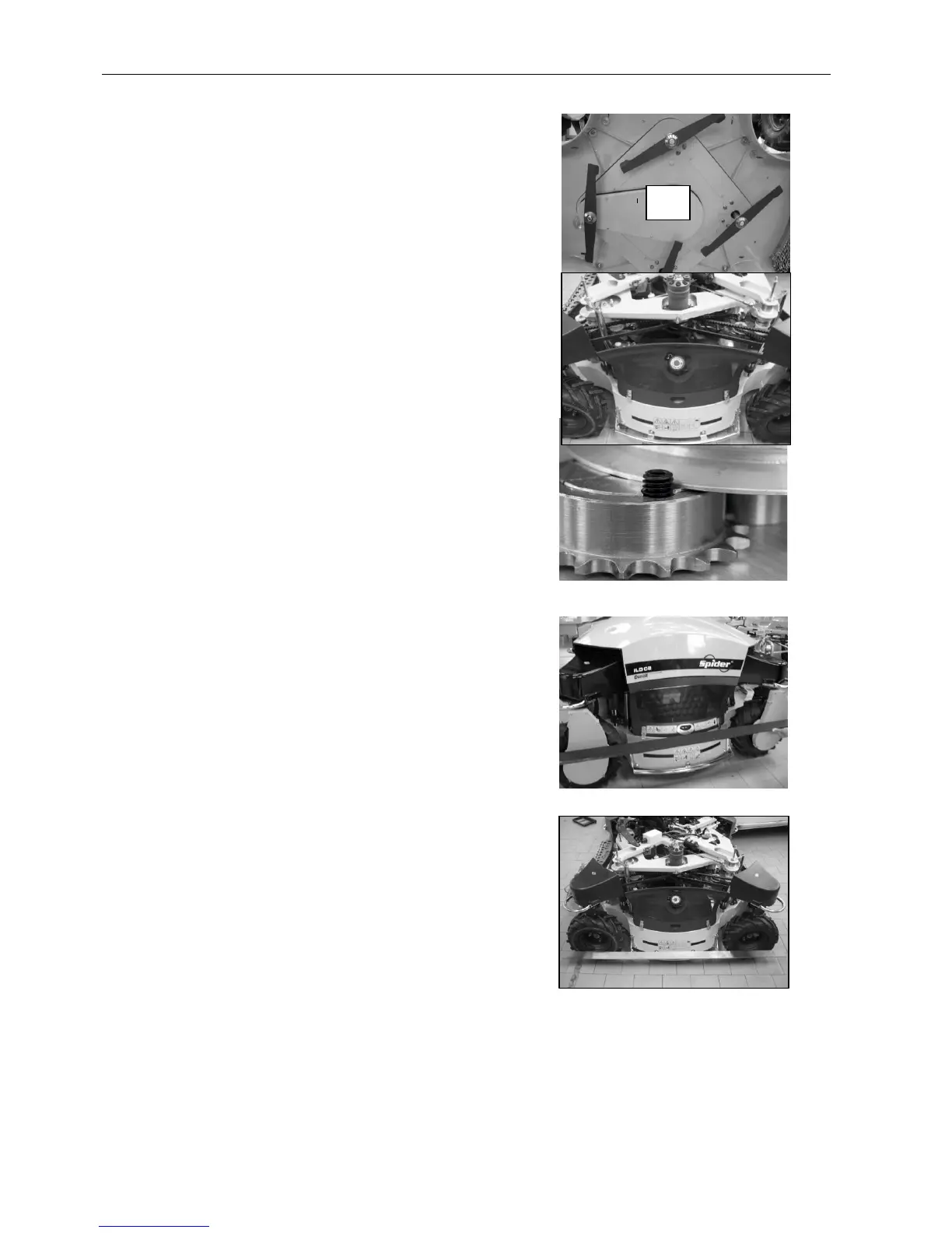
11.8 DRIVE V-BELTS
Check the wear and tension of the V-belts and
the tensioning devices.
a) Hydraulic pump drive
Located under the cutter deck inside cover (A).
The V-belt is tensioned by a belt pulley. To
tighten the belt dismount the belt pulley and
remove the required number of spacers.
b) Travel wheels drive
The V-belts are tension by shifting the hydraulic
motors.
11.9 GEOMETRY ADJUSTMENT
If you do not possess necessary equipment and
skills, have this work performed by an authorized
service/dealer
- Lift the mower (wheels above ground) and
position the wheels into a straight direction
- Release the steering chain taper lock (figure
91)
- Place a straight lath to the wheel portal on the
left side and to the tyre disc on the right side
and adjust the wheels so that they are parallel
(figure 92, figure 93)
- Tighten at least 1 screw of the taper lock
(whichever is accessible). Do not turn the
wheels unless you have tightened at least one
screw - this would distort the geometry!
- After tightening one screw you can turn the
wheels
- Tighter the second screw
- Check the geometry with a lath
- Step-by-step turn wheels and tighten both
screws of the taper locks of all wheels until
they are completely tightened (approx. 23 Nm)
Figure 91.
Figure 92.
Figure 93.