IM-P706-03 CTLS Issue 1
10
SP7-20 Smart Positioner
2.3 Operating principle
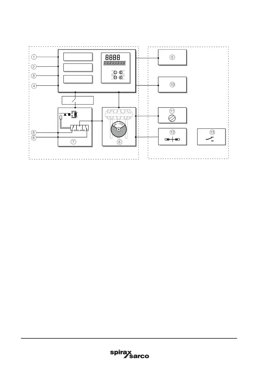
Fig. 1 Schematic diagram
Basic device
1 LCI plug *
2 Setpoint signal 4 to 20 mA/bus connection 9
to 32 Vdc
3 Binary input *
4 Binary output *
5 Supply air: 1.4 to 6 bar (20 to 90 psi)
6 Exhaust
7 I/P module with 3/3-way valve
8 Position sensor
(optional up to 270° rotation angle)
Note : With optional upgrades either, the ‘Installation kit for digital feedback with proximity switches’ (13) or
the ‘Installation kit for digital feedback with 24 V microswitches’ (14) can be used.
In both cases though, the mechanical position indication (12) must be installed.
2.4 Principle of operation
The SP7-20, SP7-21, SP7-22 is an electronically configurable positioner with communication capabilities
designed for mounting on pneumatic linear or rotary actuators.
Fully automatic determination of the control parameters and adaptation to the positioner allow for considerable
time savings as well as optimum control behavior.
Optional upgrades
9 Plug-in module analog feedback (4 to 20 mA) *
10 Plug-in module for digital feedback *
11 Installation kit for mechanical position indication
12 Installation kit for digital feedback with proximity
switches
13 Installation kit for digital feedback with 24 V
microswitches
* Only for devices with HART Communication.

 Loading...


