IM-P706-03 CTLS Issue 1
22
SP7-20 Smart Positioner
3.2 Electrical connections
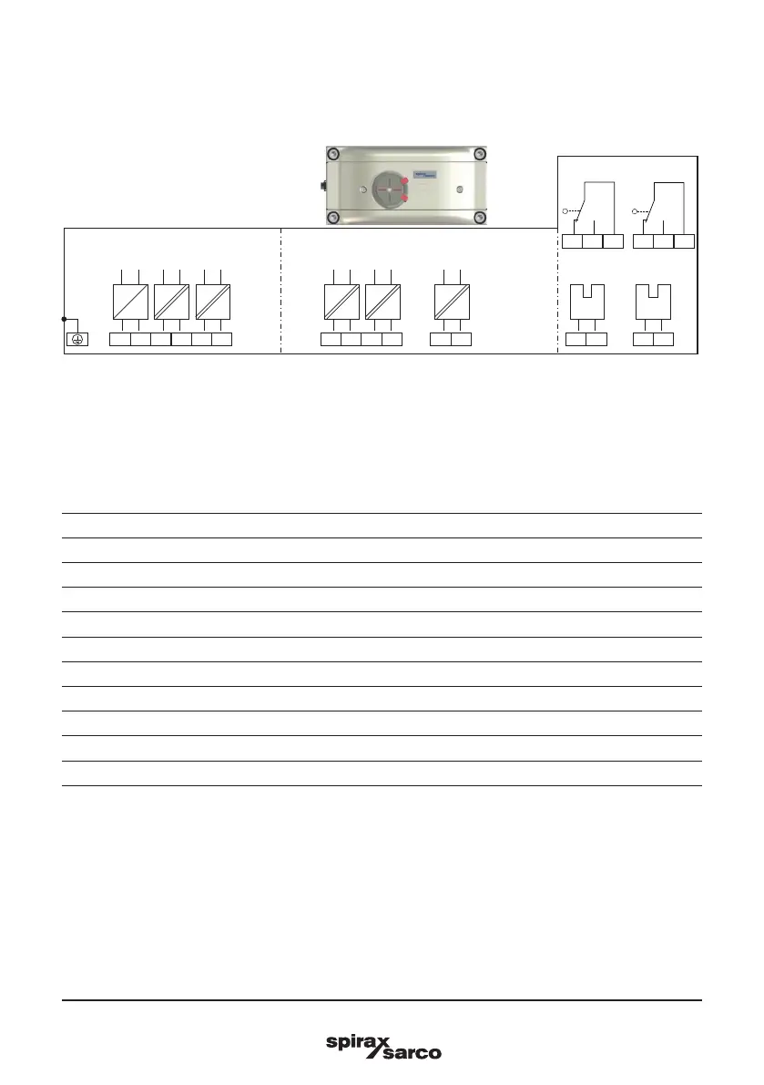
3.2.1 Positioner SP7-20 Electrical Connection
Fig. 16
A Basic device
B Options
C Options, limit switch with proximity switches or microswitches
Connections for inputs and outputs
Terminal Function/comments
+11/−12 Analog input
+81/−82 Binary input DI
+83/−84 Binary output DO2
+51/−52 Digital feedback SW1 (Option module)
+41/−42 Digital feedback SW2 (Option module)
+31/−32 Analog feedback AO (Option module)
+51/−52 Limit switch Limit 1 with proximity switch (Option)
+41/−42 Limit switch Limit 2 with proximity switch (Option)
41/42/43 Limit switch Limit 1 with microswitch (Option)
51/52/53 Limit switch Limit 2 with microswitch (Option)
Note : The SP7-2X can be fitted either with proximity switches or microswitches as limit switches. It is not
possible to combine both variants.
M1
+11
-12
+81
-82
+83 -84
DI DOAI
+51 -52
SW2
+41 -42
SW1
+31 -32
AO
BA
+51 -52 +41 -42
41
42
43
51
52
53
C
Limit 1 Limit 2
Limit 1 Limit 2