IM-P706-03 CTLS Issue 1
27
SP7-20 Smart Positioner
3.3 Connection on the device
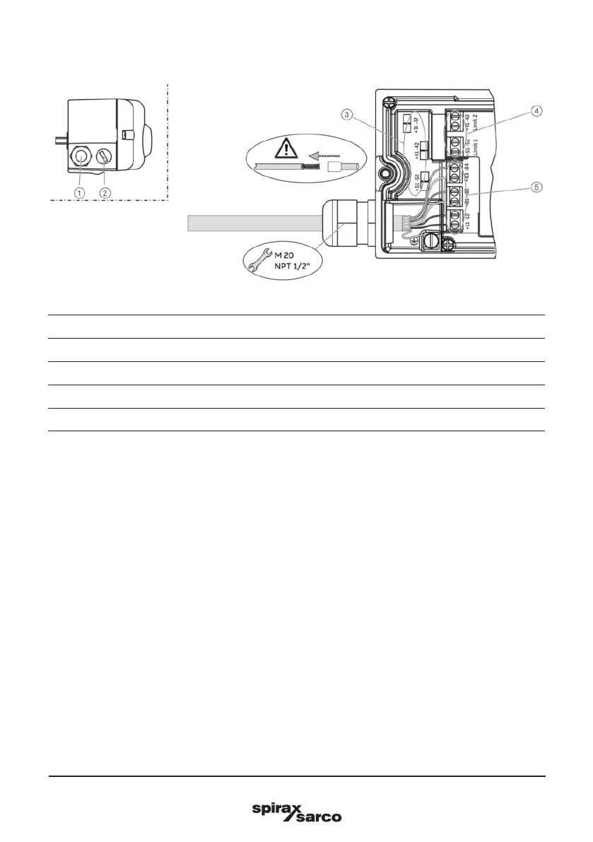
Fig. 18
1 Cable gland
2 Blind plug
3 Terminals for option modules
4 Terminal attachment kit for digital feedback
5 Terminals for basic unit
2 tap holes ½ 14 NPT or M20 × 1.5 are provided on the left side of the housing for cable entry in the
housing. One of the tap holes is fitted with a cable gland, while the other tap hole has a blind plug.
Note
The connecting terminals are delivered closed and must be unscrewed before inserting the wire.
1. Strip the wires to approximately 6 mm (0.24").
2. Connect the wires to the connecting terminals in line with the connection diagram.