4.3 Jumper Selection
The TITAN ECU has standard harnesses for all engine configurations. The two basic groups of
sensors require 12V for Hall and Optic sensors and 5V for Magnetic sensors. This selection
between the supply voltages is done by jumper settings. There is also a stronger pull-up resistor
required for the hall or Optic sensors and they are also selected with the Jumpers. See the
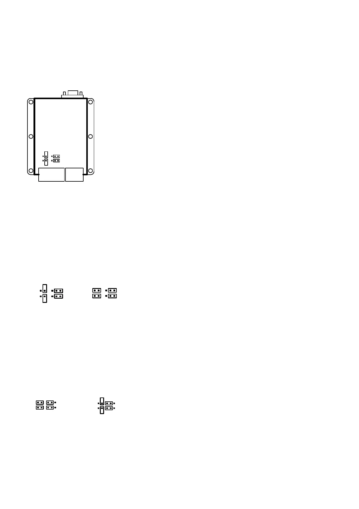
illustrations on how to set these jumpers correctly for you application.
12 Way
10 Way
TITAN ECU
JP1
JP3
JP2
JP4
4.3.1 Trigger Sensor
JP 1 and JP2 are used for this pickup.
4.3.2 TDC Sensor
JP 3 and JP4 are used for this pickup.
4.3.3 Magnetic Sensors
With this sensor JP2 & JP4 acts as a filter resistor which is only used if interference is detected on
the RPM signal.
JP1 & JP2 are always set to 5V as in the drawing.
JP1
JP3
JP2
JP4
JP1
JP3
JP2
JP4
Magnetic
2K2 Filter Off
Magnetic
2K2 Filter On
4.3.4 Hall / Optic Sensors
With these sensors JP2 & JP4 acts as a Pull-Up resistor which is normally on. If the sensor has a
weak signal these jumpers may be selected to Off to reduce load on them.
JP1 & JP2 are always set to 12V as in the drawing.
JP1
JP3
JP2
JP4
Hall / Optic
2K2 Pull-Up On
JP1
JP3
JP2
JP4
Hall / Optic
2K2 Pull-Up Off
4.4 Installing Procedure of the ECU
• Locate a convenient mounting position for the ECU inside the cab for water protection.
Humidity and heavy duty service units are available on request and will be custom made.