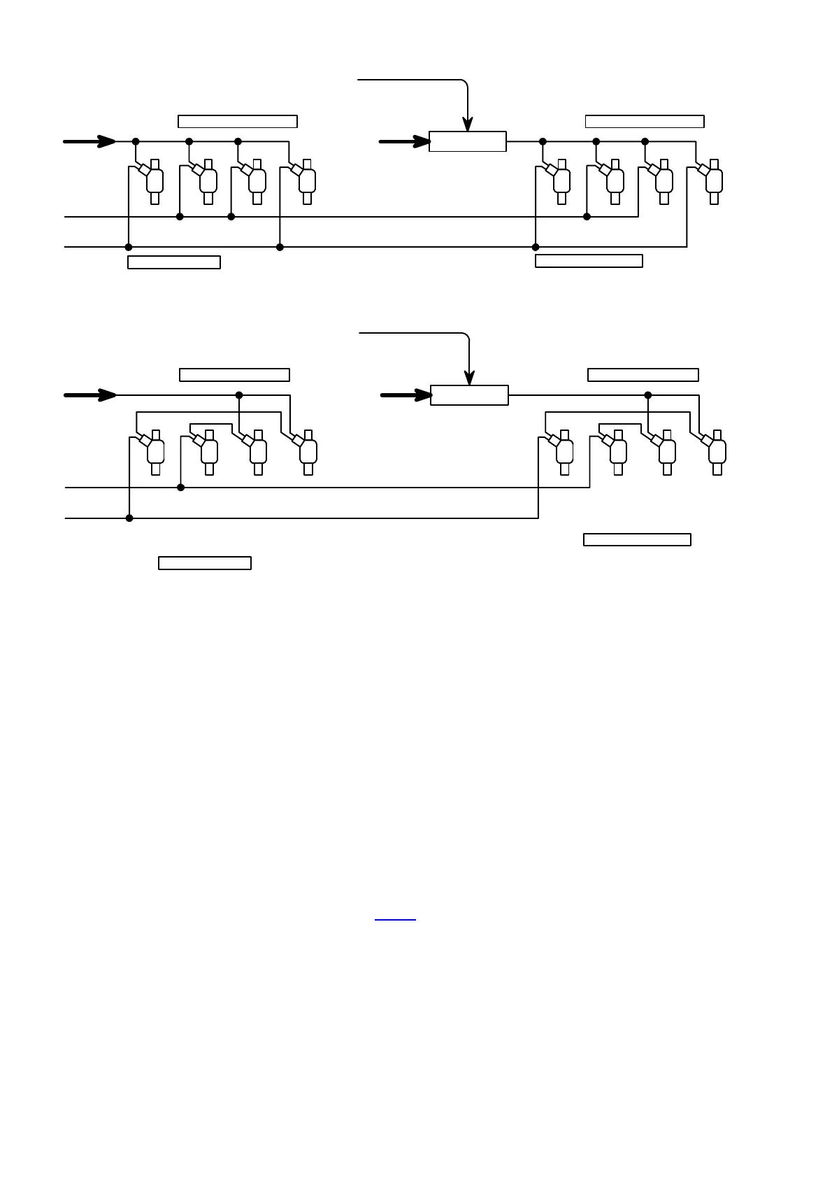
R1+
Inj1 White
Inj 2 Black
1
2
3
4
4Cyl High Imp 15 Ohm
R1+
1
2
3
4
4Cyl High Imp 15 Ohm
Primary Injectors
Secondary Injectors
From GP1 or GP2
Mosfet Switch
R1+
Inj1 White
Inj 2 Black
1
2
3
4
4Cyl Low Imp 3 Ohm
NB! Connect the Positive to the
Negative between injectors
1
2
3
4
4Cyl Low Imp 3 Ohm
NB! Connect the Positive to the
Negative between injectors
Primary Injectors
Secondary Injectors
R1+
From GP1 or GP2
Mosfet Switch
4.10 Additional Wiring
Connect all wires as per wiring schematic and according to the labels on the wiring harness.
You need to get an ignition positive from the cars existing harness and connect that to the 2 RED
power wires of the ECU (one on each of the two connectors), the gearbox computer (12 way
connector) and the Idle computer. Make sure this is Ignition power and not accessory power. Also
ensure that there is no voltage drop when the system runs.
Connect the green wire to the green wire of the Idle Control computer and the Gearbox computer.
Rev-Counters
Electronic Rev Counters must be connected to the green rev counter output wire of the ECU on
the 10 way connector. You may also need to add a pull-up resistor to get it to work correctly. See
the drawing below. Also see the software setup for this output. Note that only on the Lexus V8
Firmware the rev counter works differently than other programs.
 Loading...