4.8 Launch Control
Launch control is standard software on all 3 ECU boxes. The buttons however can be bought
optional or made up by you. The launch limits consist of an additional rev limiter which is lower
than the engine protection limiter. It will retard the timing to a value near TDC and will enrich the
fuel mixture by a set percentage. These three values can be set to the customer specs. If launch is
activated in the software, it can operate on 2 ways:
1. If only the dashboard button is connected, it activates while the button is pressed and
deactivate when the button is released. The launch limits are only applied above 4000
RPM’s.
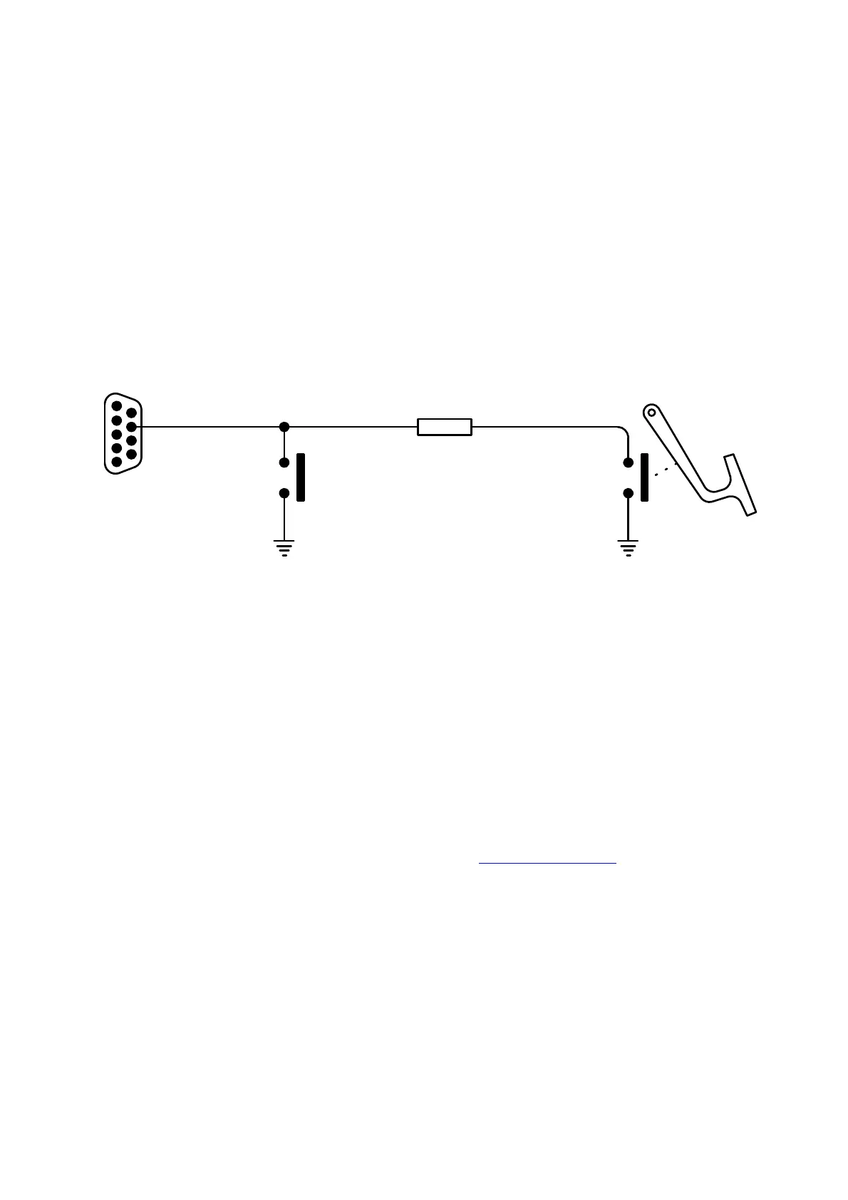
2. If the clutch pedal switch with the 10K resistor is used with the dashboard switch, the clutch
is first pressed to the floor activating the switch. Then the dashboard switch is pressed
latching the launch software. If the revs go above 4000, the launch limits are activated. The
moment the clutch is released, launch control is deactivated and normal management
presumes.
4.8 Micro Fueling
1
5
8
10K Resistor
Dash Board
Push Button NO
Clutch Pedal
Micro Switch NO
9 Pin D-Sub
Male Connector
Pin View
Note: Pin 8 can also be connected with the PC interface
cable for tuning while using the button.
This feature allows the user to use dual injectors on an engine. Only the primary injectors operate
at low load to ease tuning in town driving or low throttle driving where on high load the both the
primary and secondary injectors operates to add more fuel for racing or full throttle driving. The
TITAN ECU has only 6 drivers, so to activate this feature it uses one of the GP outputs to switch
the power to the secondary injectors on or off. This is done with an external Mosfet which is
purchased separately from the agent. The secondary injector negatives are connected with the
primary injector negatives on the same cylinders. Note there is a difference in wiring between low
and high impedance injectors. See also the different Software Settings further in the manual.
Below is a sample of the wiring required for high and low impedance injectors with the Mosfet
Switch. See your CD or contact your agent for more drawings on other engine combinations if
required.