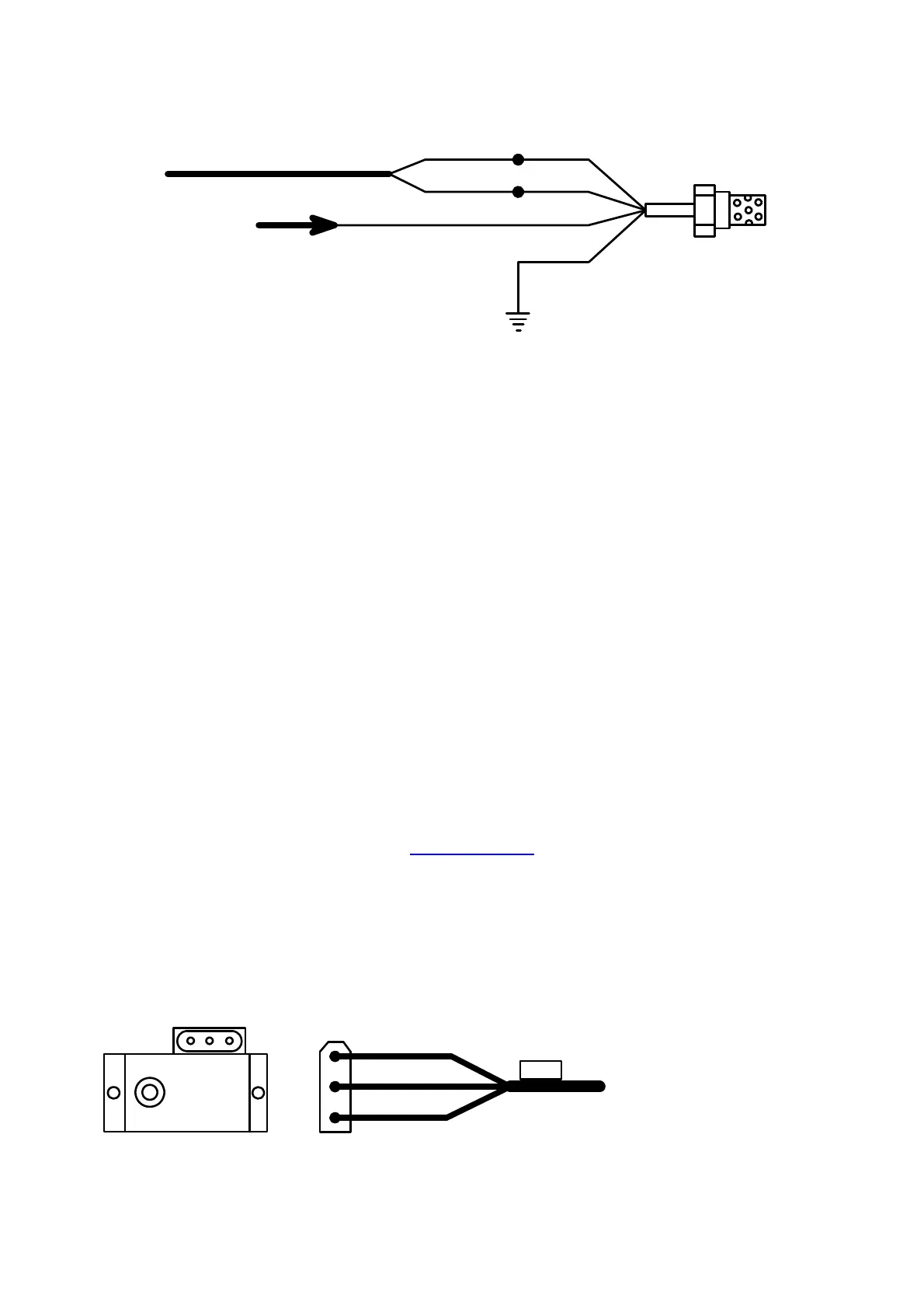
Red
Lamda
Blue
Black
Grey
White
White
R1+
Lamda
From ECU
4 Wire Lamda Sensor Wiring
Fuse Box
4 Wire Lambda
Testing a Lambda Sensor for the Correct Pin-Outs
Test the resistance with an Ohm Meter between 2 pins at a time. The element normally has the
same colors and has a resistance of 6 to 12 Ohm. When you find the element connect it to ground
and 12 volt as above. It does not matter which wire is which as it is only an element. The sensor
part can only be measured on the car when it is working. So connect the two remaining wires to
the lambda cable as explained above. Test it when the engine is hot. If it does not work swop the
sensor wires and test it again. This will not damage the sensor if connected wrong.
4.6.6 Water and Air Temperature Sensor
• Always use a 2 wire sensor and connect the one wire to the sensors cable white and the
other to the relevant sensor input wire. This will prevent ground interference with the engine
currents. It your sensor is broken you can replace the water temperature sensor with a 2K
NTC Resistor and the air temperature sensor with a 10K NTC Resistor. To test them have
them at a temperature of 20°C and then they should read the resistance they are specified
for.
4.6.7 Map Sensor
The map sensor is an external unit and can be any variety. We supply 3 basic types depending on
stock availability or value required by the customer. The sensors have different values and must
be calibrated. The vacuum or boost rating of the sensor must be entered in the software to get the
scales correct. (See Map calibration under Active Sensors)
Always connect the Map sensor as close to the engine as possible. Do not join it to other vacuum
lines. It would delay the vacuum signal and cause flat spots or over fueling. Connect it to a 3 mm
minimum ID pipe directly to the intake manifold.
• The most popular one is the GM replacement sensor that comes in 1Bar and 3Bar versions.
It may also be soldered to a more popular connector. Ensure that the wiring for this sensor
is correct. Old versions of the 3Bar was 12V but the new batch is all 5Volt.
+ s -
5V & 12V
Map Sensor
Blue
Black
Red
+
S
-
Map
To ECU
• The second Map sensor is the Motorola MPX4…AP series. It is a bit more expensive but
more freely available. These are 5V sensors and come in 1Bar and 2.5Bar arrangements.
The connector is soldered on in-house and is different to the first one to the pin