• Remember this is a guideline to black box testing and not a failsafe operation. Note point 4
above and rather consult the specifications from the manufacturer or vehicle diagrams.
4.6.3 Throttle Position Sensor
• The TPS must operate through the whole range of the throttle movement to ensure that the
ECU can measure the whole of the movement.
• The TPS must be calibrated in the PC software as certain features like idle control, prime
pulse, flood control and fuel cutoff require certain positions of the throttle to operate
correctly. This is done in the setup menu before starting the engine. (see TPS calibration
under Active Sensors)
• The sensor is connected to 5V, ground and signal input. Connecting it wrong may damage
the ECU or TPS as you may short the 5V to ground. Test it before you connect it to the
ECU.
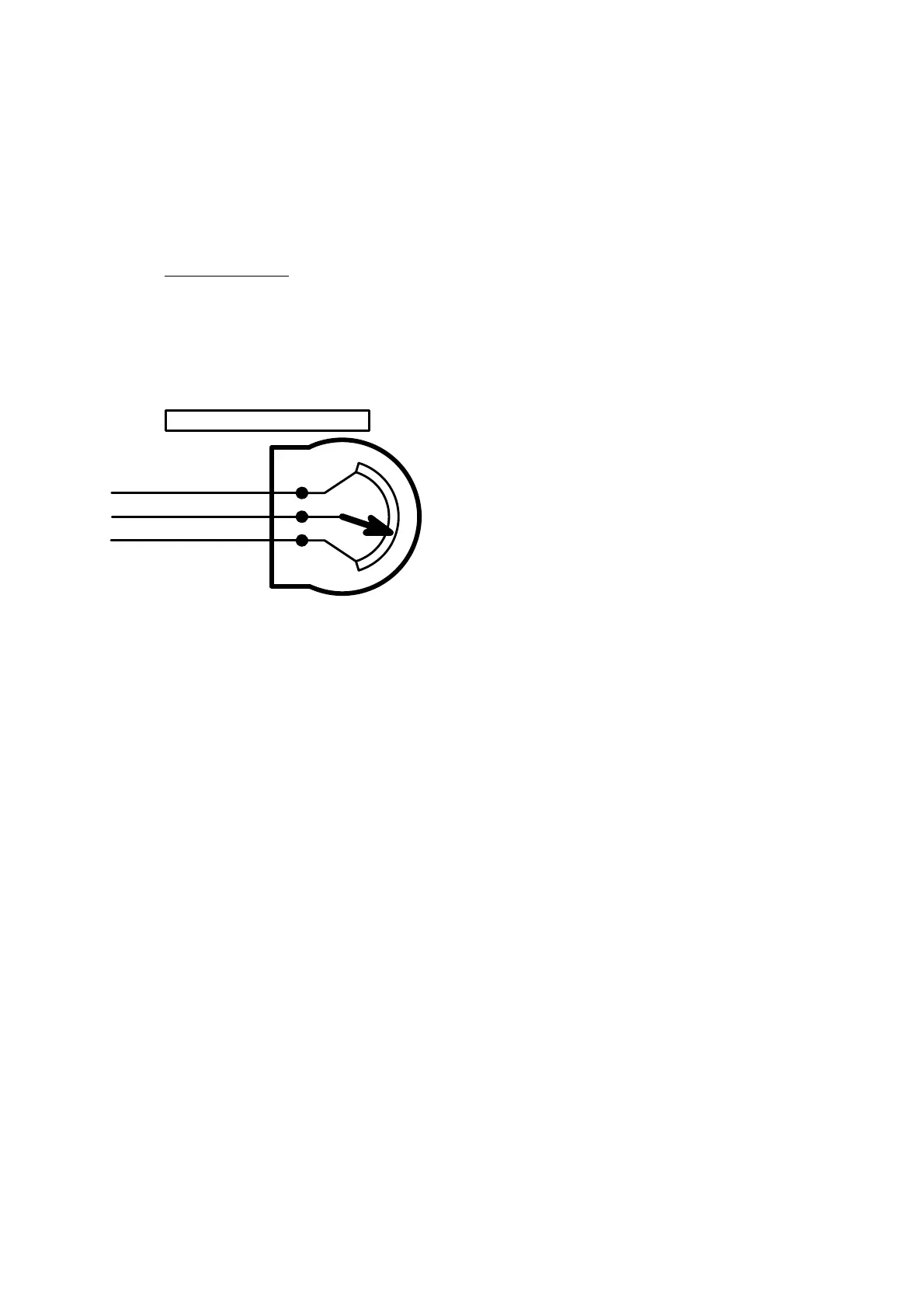
4.6.4 Testing a TPS for the Correct Pin-Outs
•
Red +5V
Blue
Black / Screen
Close
Open
Throttle Position Sensor
C
B
A
1. Test the resistance with an Ohm Meter between 2 pins at a time. Each time move the
throttle open and close. If the resistance do not change and is approx 5000 Ohm, then you
found pin A & C. The remaining pin is B which is the wiper. Mark it as B.
2. Now test the B pin with one of the other pins. If it is below 500 Ohms then that pin is C. If it
is above 4500 Ohm that pin is A.
3. Now to double check. Measure between B & C. if the throttle is closed the resistance is
below 500 Ohm. If you open the throttle the resistance increases to above 4500 Ohm.
4. If you measure between A & C the resistance is around 5000Ohm and does not change
with throttle movement.
4.6.5 Lambda Sensor
• For the one wire lambda sensor, connect it to the red wire of the lambda cable only. For the
four wire sensor, connect the sensor wires to the red and blue wire of the lambda cable.
Sensor positive to the red wire and sensor negative to the blue wire. The element is
connected to ground and the 12V supply from the fuse box that supplies the injectors. (See
drawing). Do not earth the screen or connect the element ground to the screen. This will
induce voltage drops resulting in faulty fuel ratio readings.
• The lambda sensor used by the ECU is a narrow band sensor.