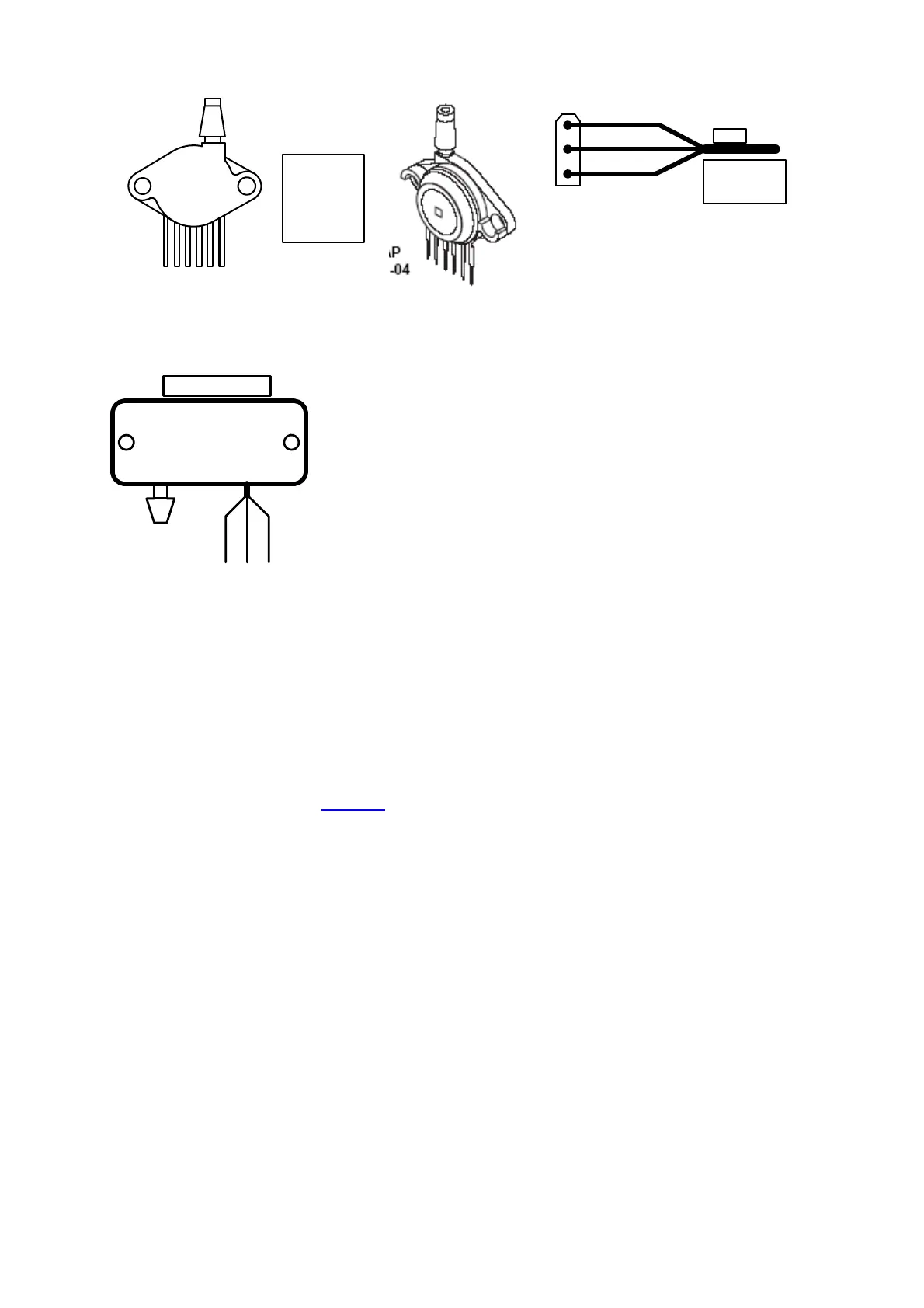
configurations. If you have a sensor with leads, connect the matching colors to each other.
Blue
Black
Red
1
2
3
Map
MPX4250AP - 2.5 Bar
MPX4115AP - 1 Bar
To EMU
1. Signal Out
2. Gnd
3. 5V Supply
4. NC
5. NC
6. NC
1
2
34
5
6
MPX4...AP
(number view)
1. 5V Supply
2. Gnd
3. Signal Out
SPITRONICS
R
e
d
B
lu
e
B
la
c
k
1 or 2.5 BAR
ENGINE MANAGMENT
MAP Sensor
• Then there is also a surface mount sensor which is 5V and comes in 1Bar and 3Bar. These
ones will be mounted on the unit’s PCB or a separate housing. No further info available at
this time.
• You can also use existing map sensors of various engine manufacturers. Ensure that you
have the correct wiring and calibration.
4.7 Idle Control
The ECU does idle control. The settings
for valve and stepper motors are different. Valve control is
done with the ECU GP outputs while stepper motors require a separate stepper control unit.
For 2 wire idle valves found on most cars, the GP 2 output will be pulse-width controlled and no
separate hardware is required. Only a free wheel diode that goes over the two pins must be
connected. See the drawing supplied on your CD. There is a black 1N4007 diode supplied in each
ECU pack.
Some 3 Wire valves require GP 1 & 2 outputs. These valves have on coil to open and one to
close. It does not have a spring system. These ones can also be done with the ECU. Normally
BMW.
Other 3 wire valves have a spring which keeps it in a certain position. The one coil opens the valve
completely and on coil closes it completely. Here a resistor is connected to the closing coil and
ground to close the valve to reach minimum idling RPM’s when hot. Then only GP out 2 is used on
the coil that opens the valve. Normally Toyota.
There is also a back feed Diode required in the ignition supply wire of the 12 Way connector. See
drawing below.