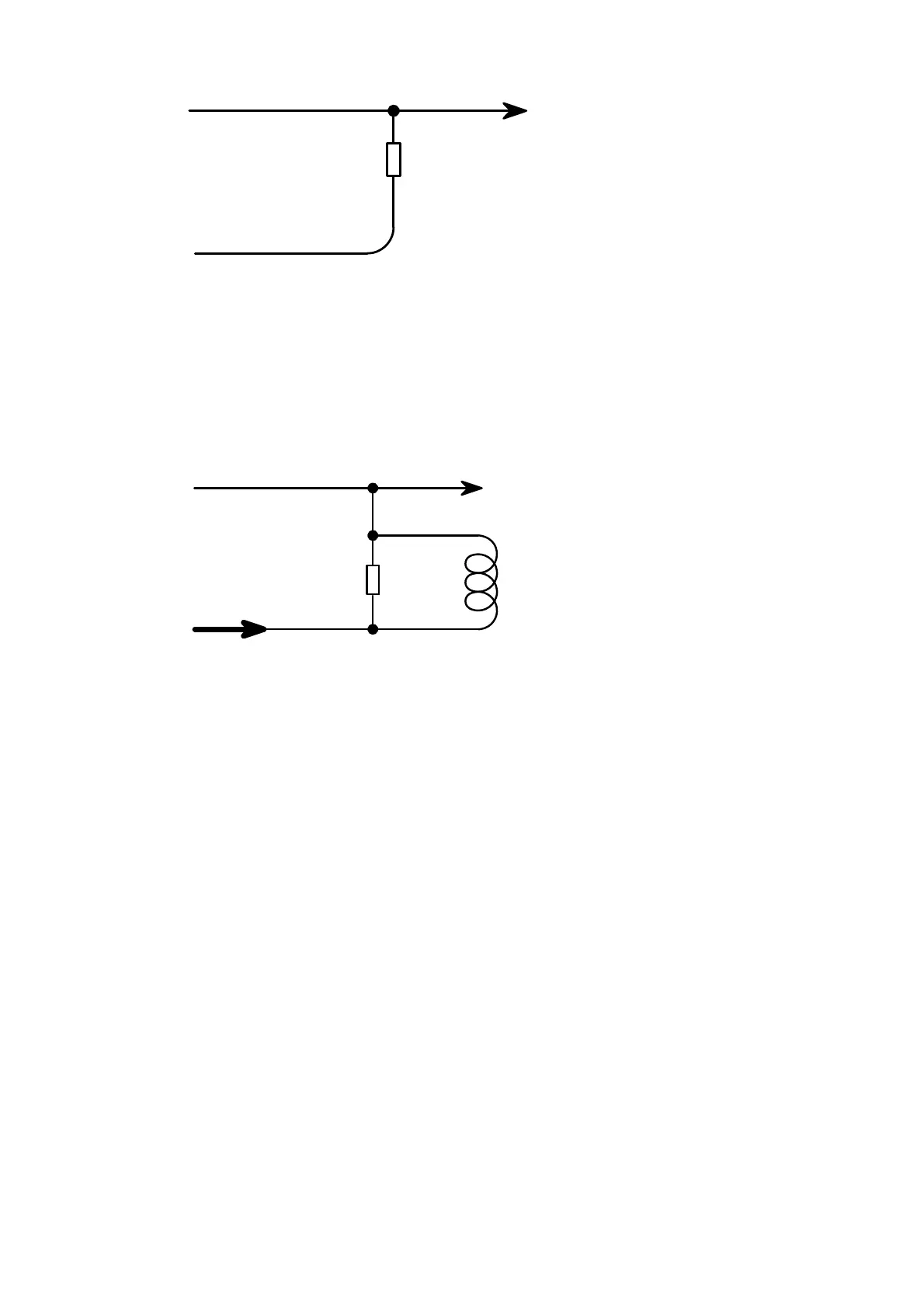
Resistor
1K Ohm
0.25W
Red
RPM Output
Green
To Revcounter
From Ignition +
Option 1
Electronic
revcounters
Coil Negative Rev Counters may not work with the above connection because they require a spike
rather than a ground signal. In this case the rev counter must be connected to coil negative. Then
you will have to calibrate the rev counter or try the circuit below. This circuit will generate a spike
for the rev counter and will work in most cases. If it still does not work try a 220 Ohm 5 watt
resistor instead.
R2+
Resistor
100 Ohm
5 Watt
From Fuse Box
Old Relay Coil
without contact plate
RPM Output
Green
85
86
To Revcounter
Option 2
Coil Negative
revcounters
Connect the yellow TPS output wire to the yellow wire from the gearbox computer.
Run a 2.5mm
2
wire from each of the supplied relays pin 30 directly to the battery positive. Do not
common these wires. Now run a 2.5mm
2
from pin 87 to the fuse box and then to the injector
positives. Do not connect anything else on this relay or it may lean out fuel mixtures. You may
connect the 4 wire Lambda to this relay as it has a consistent power. Run a 2.5mm
2
to the fuel
pump and coil positives. Use separate fuses in this wire for protection in component failure and to
protect the ECU. See the wiring diagrams.
Now check each wiring circuit with your multi meter as described in the test procedure for each
engine on the two harness connectors. This will indicate faults in the wiring that may destroy the
ECU.
Ensure that the ECU is grounded properly as per specification. Now only connect the 12 way
harness and proceed with the PC setup. After you have wired everything in as per the schematics,
you may now connect your battery’s positive terminal and turn your ECU on. Again follow the start-
up procedure carefully.
Pin References for the ECU
The ECU has two connectors for all wiring combinations. A 12 way connector for power and
sensors, and a 10 way connector for all the outputs to the engine. Note that the ECU connects to
ground via the aluminum enclosure. It is not necessary that all the pins will be used. There may be
additional wires on the drawing that cannot be found on the pin descriptions. This is due to other