connections in the harness to ease with installation. The pin-outs are just for reference. Please
follow the labels on the wiring harness when connecting up your new ECU. All wires are grouped
gether for ease of installation.
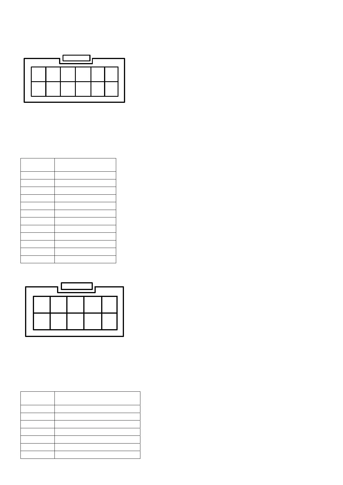
Female Plug on the ECU harness. Note the retaining clip on top
nd how the pins are numbered.
nnector
to
Figure shows a view of the 12pin
5
4321
11
10
9
8
7
6
12
Harness Connector
Pin View
a
12 way
co
1 Air temp sensor
2 TPS sensor
3 MAP sensor
4 Signal Ground
5 Sensor2 Supply +
6 Sensor1 Supply +
7 Water Temp Sensor
8 Lambda Sensor
9 5 Volt Output
10 12V Ignition In
11 Sensor 2 Input
12 Sensor 1 Input
Female Plug on the ECU harness. Note the retaining clip on top
nd how the pins are numbered.
nnector
Figure shows a view of the 10pin
5
4321
10
9
8
7
6
Harness Connector
Pin View
a
10 way
co
1 Coil 2 -
2 Injector 3 - (Coil 4 -)
3 Injector 1 -
4 Fuel Relay -
5 Gen Purpose Out 1 -
6 Coil 1 -
7 Coil 3 - (Injector 4 -)