8 Injector 2 -
9 RPM Trigger Output to ground
10 Gen Purpose Out 2 -
4.11 Coil Selection
It is important to know which coil is on the engine as a faulty setting here may destroy the ECU
driver or coil. Always start the ECU with a disconnected 10Way connecter till you set the Trigger
Level Output to the correct setting. Also start with a 5A Fuse which will blow quickly if you have the
etting wrong.
has a resistance of +/- 1.5 ohm and a
k of the ballast coil with this
ternal so that the ECU charge the coil with a negative pulse
nd fire it with a positive going pulse.
s
4.11.1 Basic Coil
This ignition is designed to use electronic as well as external ballast resistor coils as is found with
the point-condenser systems. This point-condenser coil
charge-time of 7 m/s. Do not connect the ballast resistor.
Electronic ignition coils were designed for variable dwell systems to improve spark at high Rpm’s.
They have a resistance of +/- 0.8 ohm It will improve over the spar
ignition especially for V8’engines. It has a charge time of 3 to 5 m/s.
Another coil on the market has the ballast resistor built in (+/- 3.5 ohm). This will give a poor spark
at cold starting or high Rpm’s. These coils are not recommended for performance engines and 6
Cylinders or higher. These coils have a charge time of 9 m/s. For all of the above coils the ECU
Trigger Level Output must be set to in
a
4.11.2 Composite Coil
These hard resin coils consist of single, wasted spark combination or multi coils in a single
housing, and some have built in driver electronics. If it has no driver there is usually a common pin
and one pin for each coil. To measure this coil put the meter on Ohms and measure all the points.
You should get a 0. 8Ohm reading for each coil. If you measure over the two coils it should read
1.6 Ohm. For all of the above coils the ECU Trigger Level Output must be set to internal so that
the ECU charge the coil with a negative pulse and fire it with a positive going pulse.
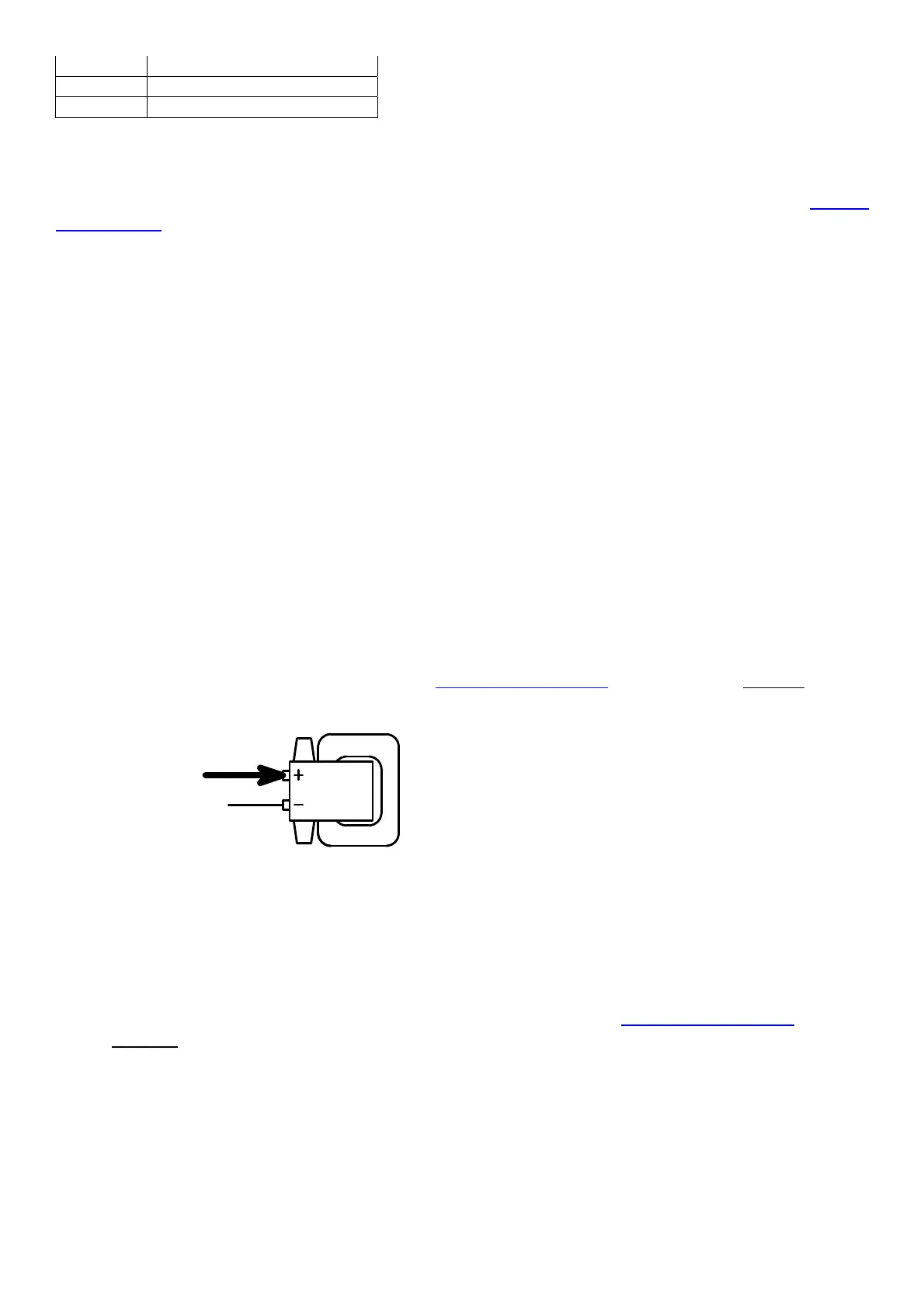
From EMU - Coils
R2+
From Fuse Box
Coil
4.11.3 Electronic Coils
If you measure high resistances or open circuit, then the coils has an internal driver. These coils
normally have a positive, ground and trigger input for each coil. These coils are normally charged
with a positive pulse and fired with a negative going pulse. Using these coils with the ECU requires
an external resistor between the trigger and positive of the coil. The reason is that the ECU only
gives a ground signal for normal coils. For all these coils the ECU Trigger Level Output must be
set to external so that the ECU charge the coil with a positive pulse and fire it with a negative
going pulse. These Coils with internal drivers can be connected two coils per output. You must
add a pull-up resistor per driver and make sure on the firing order that these coils move up en
down simultaneously.