APV_CU4 AS-i_UK-5_072018.indd
UK
Control Unit
CU4 AS-interface
Instruction manual: UK - rev. 5
APV
18
4. MechanicsandPneumatics
4.6. Solenoidvalves
In the base of the control unit max. 3 solenoid valves are installed.
The 3/2-way solenoid valves are connected with the electronic
module by moulded cables and plug connectors.
Control: effected by pwm-signal
Lever: rotary switch at valve
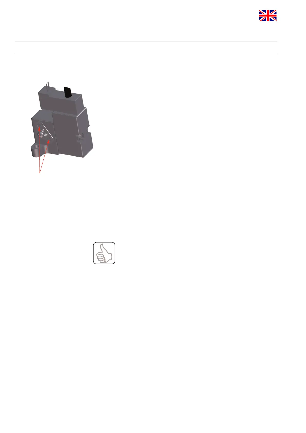
4.7. Throttlingfunction
The operating speed of the valve actuator can be varied or reduced.
This may be necessary to slacken the actuation of the valve in order
to prevent pressure hammers in the piping installation. For this
purpose, the supply and exhaust air of the rstsolenoidvalve can
be adjusted via the throttling screws respectively allocated in the
interface of the solenoid valve.
By turning the screws in anticlockwise direction, the inlet or outlet air
is throttled
4.8. NOTelement
Through the installation of the logic NOT element, the closing force
of the valve actuator can be increased by additional compressed air.
The NOT element conveys the compressed air via an external
reducingvalve(max.5bar)tothespringsideofthevalveactuator.
Thepressurereducingvalveisxedto5bar.
Note:
The air connection of the NOT element is equipped with an
integrated non-return valve.
The air hose must be slided into the air connection until it stops in
order to open the non-return valve.
The NOT element is also used for air/air actuators.
throttling screws
 Loading...