APV_CU4 AS-i_UK-5_072018.indd
UK
Control Unit
CU4 AS-interface
Instruction manual: UK - rev. 5
APV
21
6. Electronic module
6.1.1 Switch-overoffeedbacksignals
The signals to the control can be switched over via the bridge
between the terminals 10, 11 and 12.
Ifabridgeislocatedbetweentheterminals10and11(normal),the
signal is transferred from sensor 1 (closedvalveposition) to input
DI0 of the control. The signal of sensor 2 (openvalveposition)is
sent to input DI1.
Incaseofabridgebetweenterminals11and12(reverse),the
signal of sensor 1 (closedvalveposition) is sent to input DI1
of the control. At input DO0, the signal of sensor 2 (openvalve
position) switched.
If there is no bridge between the terminals 10, 11 and 12, this will
lead to an error message.
The two LEDs 'valve open' and 'valve closed'willashinthis
case.
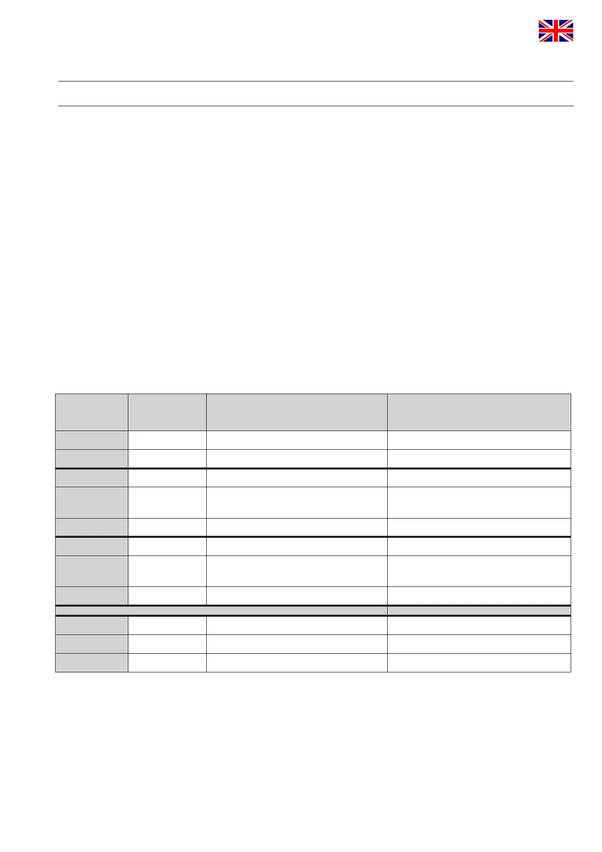
6.2. Functional description of connections
Terminal Designation
Functional description
for all valve types
Funtional description
forD4,D4SLandDA4valvetypes
1 AS-i + AS-i network connection AS-i network connection
2 AS-i - AS-i network connection AS-i network connection
3 5 VDC voltage supply for valve sensor voltage supply for valve sensor
4 Sensor 1
sensor signal 1
(closedvalveposition)
connection Hall sensor 3
(closedvalveposition)
5 GND ground for sensor supply
6 5 VDC voltage supply for valve sensor voltage supply for valve sensor
7 Sensor 2
sensor signal 2
(openvalveposition)
connection Hall sensor 2
(openvalveposition)
8 GND ground for sensor supply ground for sensor supply
10 Normal normal allocation of feedback signals normal allocation of feedback signals
11 Feedback tie point for cable bridge tie point for cable bridge
12 Reverse reverse allocation of feedback signals reverse allocation of feedback signals
 Loading...