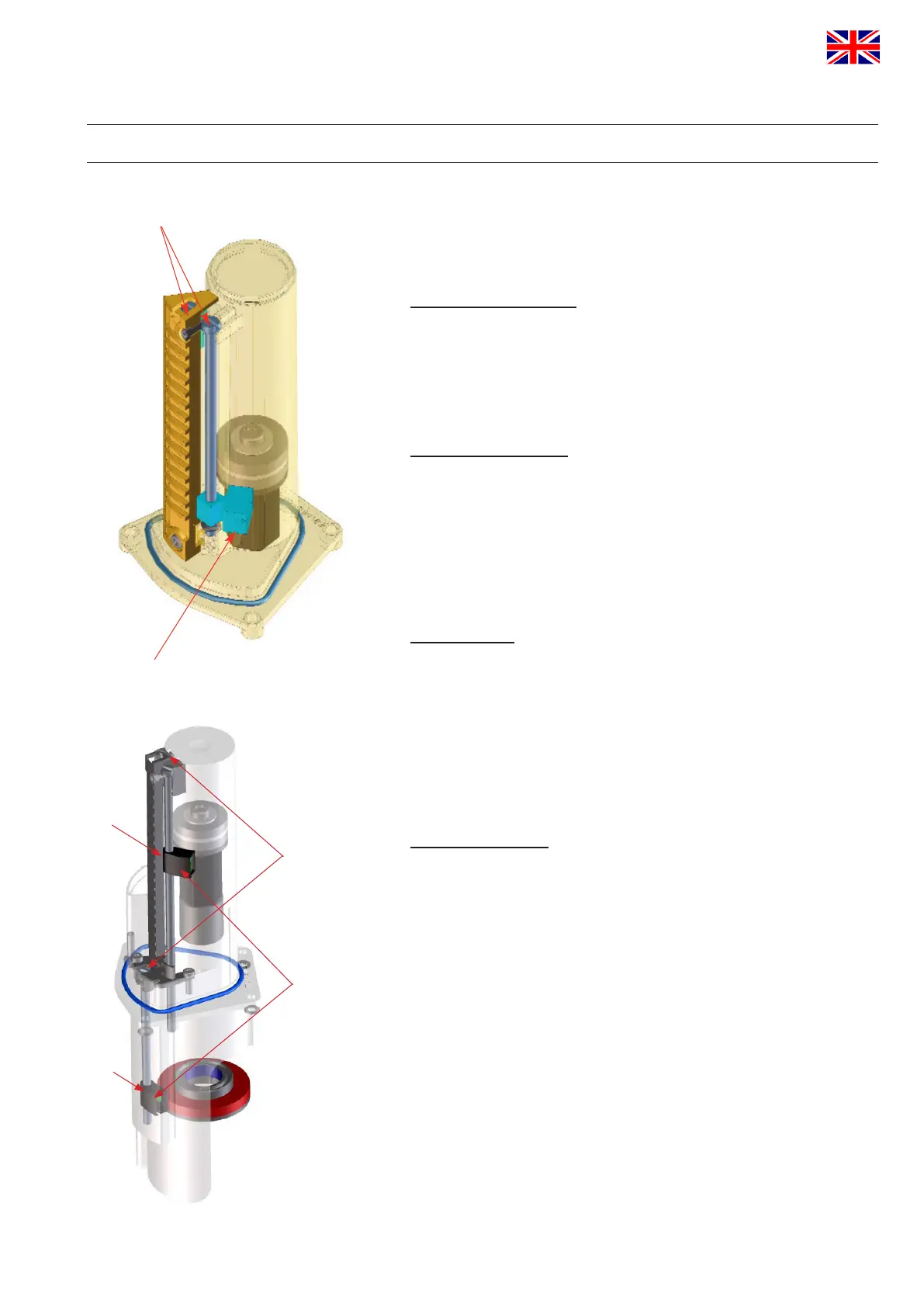
adjusting screws
Hall effect sensor
Feedback unit for
SPX FLOW APV valves
Hall effect
sensors
adjustment
screws
S2
S3
Feedback unit for
SPX FLOW APV / WCB D4 valves
APV_CU4 AS-i_UK-5_072018.indd
UK
Control Unit
CU4 AS-interface
Instruction manual: UK - rev. 5
APV
41
10. Service
10.1. Dismantling
Before disassembly, verify the following items:
• Thevalvemustbeinsafetypositionandmustnotbecontrolled!
• Shutoffairsupply!
• Cutoffcurrenttocontrolunit,i.e.interruptthesupplyvoltage!
Solenoidvalve(4,5,6)
+ Open the CU cover by turning in anticlockwise direction.
+ Release the plug connection at the electronic module for the
corresponding solenoid valve.
+ Releaseandremovethe2screws(20)TX20.
+ Replace the solenoid valve.
+ Assemblyinreverseorder.Seetoapropertoftheatseal!
Electronicmodule(2)
Before releasing the cable connections make sure that all lines are
de-energised!
+ Open the CU cover by turning in anticlockwise direction.
+ Release the plug connection of the solenoid valves.
+ Release the cable from the terminal strip, all terminals 1-15.
+ Releaseandremovethe3screws(20)TX20.
+ Replace the electronic module.
+ Assembly in reverse order.
Feedback unit
Before releasing the cable connections make sure that all lines
are de-energised!
+ Open the cover.
+ Release the cable for the Hall effect sensors from the terminal
strip, terminals 3-8.
+ Release the clamp ring and lift the CU4 from the adapter.
+ Removethe4screws(9)TX15atthelowersideofthe
CUbase(1).
+ Take out the feedback unit to the bottom.
Hall effect sensors
The Hall effect sensors can only be replaced at the dismantled
feedback unit.
+ Removethe3screws(14)TX10.
+ Removethetowerlid(13).
+ Removetheo-rings(11).
+ Dismantlethesensorsbyturningoftheadjustingscrew(12).
To simplify adjustment of feedbacks:
+ Mark the position of the sensor on the adjusting screw!
+ Assembly in reverse order.
+ Check the correct position of the Hall effect sensors and their
functions as described in chapter 8 CU assembly and startup.
 Loading...