APV_CU4 AS-i_UK-5_072018.indd
UK
Control Unit
CU4 AS-interface
Instruction manual: UK - rev. 5
APV
3
Content Page
1. AbbreviationsandDenitions 4
2. SafetyInstructions 4
2.1. Sentinels
2.2. Intended Use
2.3. General Regulations for Careful Handling
2.4. Welding instructions
2.5. Persons
2.6. Warranty
2.7 Important Safety Instructions for AS-interface networks
3. General Terms 7
3.1. Purpose of use
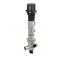
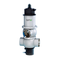
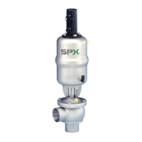
3.2. Design of CU4 AS-interface
3.3. Function of the individual components
4. MechanicsandPneumatics 10
4.1. Air connection for valves with turning actuator
4.2. Air connections for single seat and double seat mix proof valves
4.3. Pressure relief valve
4.4 Functional description - block diagrams
4.5. Technical Data / Standards
4.6. Solenoid valves
4.7. Throttling function
4.8. NOT element
5. Adapter 19
5.1. Valveswithturningactuator,e.g.butteryvalves
5.2. Single seat valves
5.3. Double seat mix proof valves DE3, DA3+
5.4 Double seat mix proof valves D4, D4 SL, DA4
6. Electronicmodule 20
6.1. Function / Block diagram
6.2. Functional description of connections
6.3. Use of data bits
6.4. Technical Data
6.5. Connections
6.6. LED indication
7. Feedback unit 26
7.1. General terms
7.2. Sensors
7.3. Adjustment of valve position feedback
7.4. Use of external sensors
8. CU Assembly and Startup 27
8.1. Valveswithturningactuator,e.g.butteryvalves
8.2. Single seat valves
8.3. Double seat mix proof valves DE3, DA3+
8.4. Double seat mix proof valves D4, D4 SL, DA4
8.5. Replacement of a CU3 control unit
9. AccessoriesandTools 40
10. Service 41
10.1. Dismantling
11. TroubleShooting 42
12. Spare Parts Lists
ITISESSENTIALTOREADTHISINSTRUCTIONMANUAL
BEFORE USE OF THE CONTROL UNIT!
 Loading...