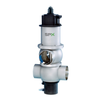
Feedback unit for
SPX FLOW APV valves
Hall effect sensors
adjustment screws
S2
S3
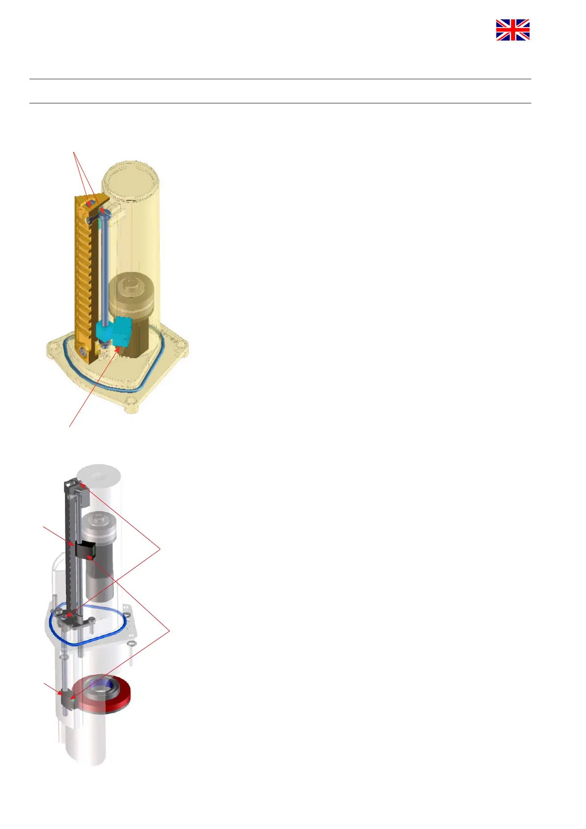
Feedback unit for
SPX FLOW APV / WCB D4 valves
APV_CU4 AS-i_UK-5_072018.indd
UK
Control Unit
CU4 AS-interface
Instruction manual: UK - rev. 5
APV
26
7. Feedback unit
7.1. General terms
For the internal registration of the valve position indication, the
feedback unit with 2 Hall effect sensors is applied. It is used when
singleseatandbutteryvalvesareinstalled.
The control of these sensors is effected by magnets assembled
on the valve shaft rod. The Hall effect sensors are installed on a
movable threaded rod. By means of this assembly, the sensors can
be adjusted via a large range, in accordance with the valve stroke.
7.2. Sensors
Halleffectsensors(APVvalves):H320385
Halleffectsesonrs(APV/WCBD4valves):H337014
UB 4,75-5,25 VDC
operatingdistanceaccordingtoSPXFLOWspecication
7.3. Adjustment of valve position feedback
By turning of the adjustment screws on which the Hall effect sensors
are installed, the sensors can be moved into the respectively
required position to detect the valve position.
The o-rings on the adjusting srews prevent unintended accidental
displacement of these positions. After the installation of the control
unit, check the correct adjustment of the position of the Hall sensor.
7.4. Useofexternalsensors
Instead of the internal Hall effect sensors, also 2 external proximity
switches can be connected to the CU4 DC, e.g. for the valve
position indication at double seat valves.
Proximity switch: H208844
UB 4,75-5,25 VDC
operatingdistanceaccordingtoSPXFLOWspecication
adjustment screws
Hall effect sensor
 Loading...