8. CU Assembly and Startup
8.4. DoubleseatmixproofvalvesD4,D4SL,DA4
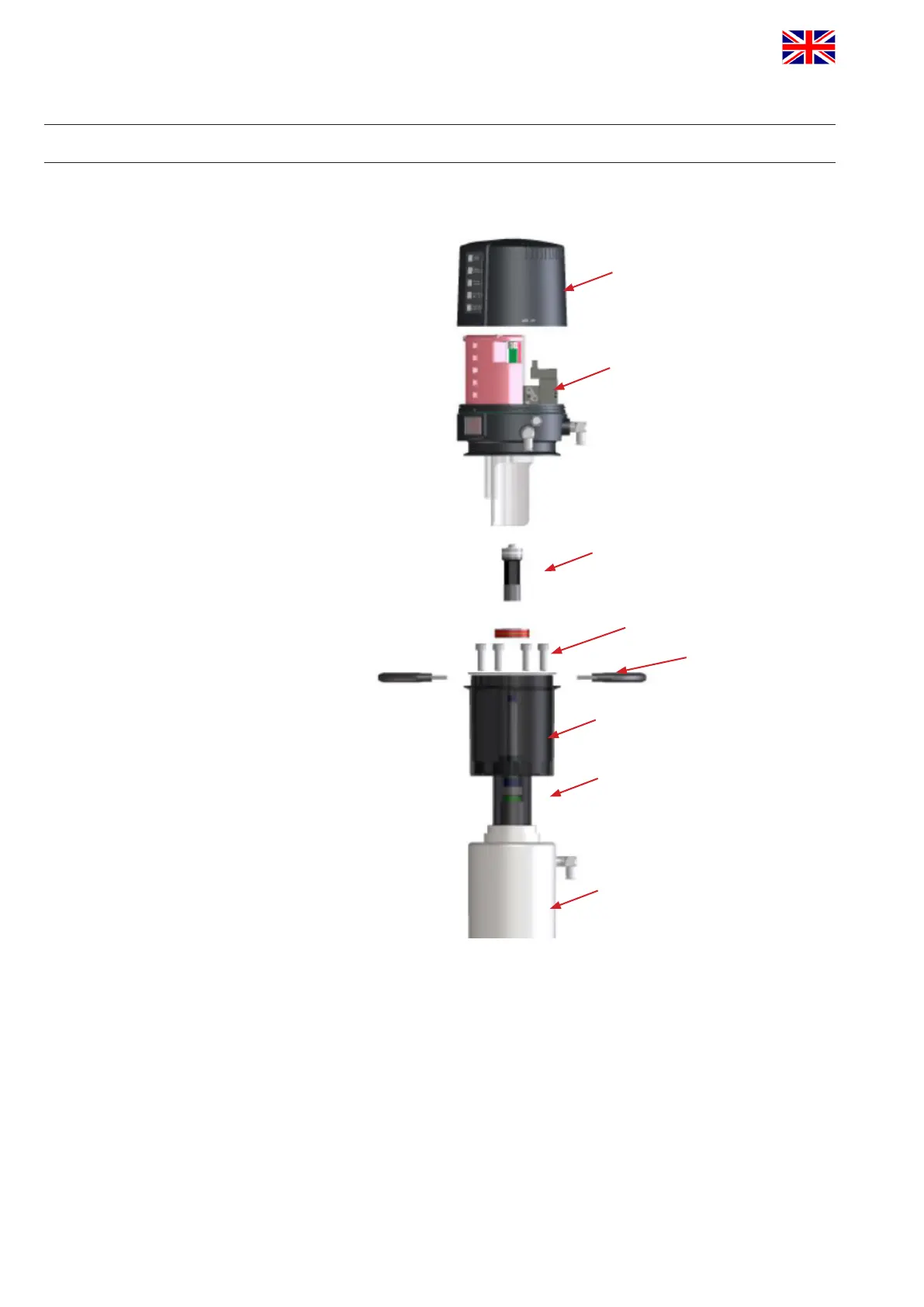
Assemblyofthecontrolunitonthevalve
1. Assemble the magnet M2 on the upper shaft under the stop screw.
2. Assemble the adapter with the 4 screws on the double seat valve.
3. Assemble the operating cam M1 with guide rod extension on the
guide rod.
4. Place the control unit onto the adapter. Observe alignment!
5. Attach the clamp rings and fasten them with the 2 screws.
6. Align air connections of the control unit to the valve actuator.
CU cover
CU41/CU43
screws
clamp ring
actuator
adapter
operating cam with magnet M1
operating cam with magnet M2
APV_CU4 AS-i_UK-5_072018.indd
UK
Control Unit
CU4 AS-interface
Instruction manual: UK - rev. 5
APV
36
 Loading...