APV_CU4 AS-i_UK-5_072018.indd
UK
Control Unit
CU4 AS-interface
Instruction manual: UK - rev. 5
APV
27
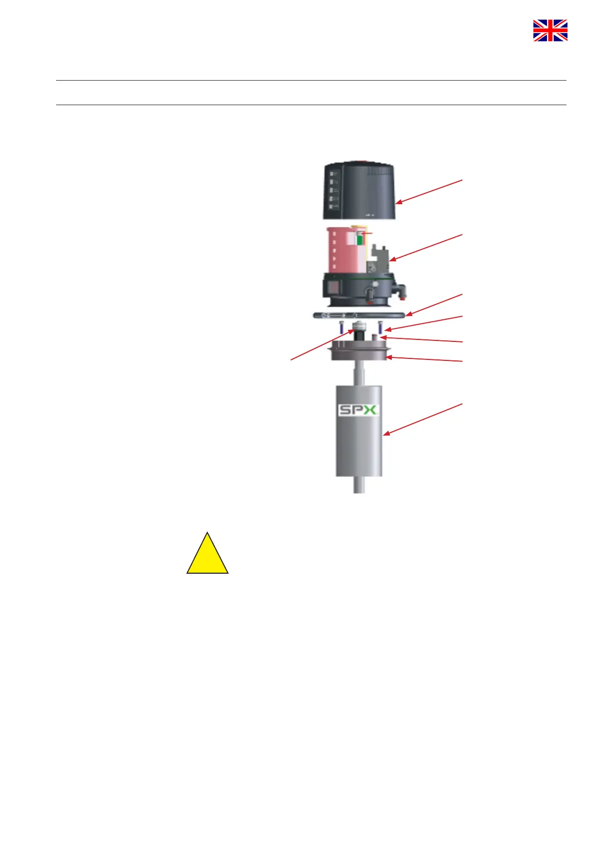
8. CU Assembly and Startup
8.1. Valveswithturningactuator,e.g.butterflyvalves
CU cover
CU base with
electronic module,
sensor tower and
solenoid valves
clamp ring
fastening screws
O-ring
adapter
actuator
operating cam with
permanent magnet
Caution!
The permanent magnet is made of fragile material and must be
protected against mechanical load. – Risk of fracture!
Themagneticeldscandamageordeletedatacarrieror
inuenceelectronicandmechaniccomponents.
Assemblyofthecontrolunitonthevalve
1. Assembly of the adapter on the turning actuator. Fasten with 3
screws. See to the right positioning of the o-rings on the lower side
of the adapter and in the groove of the air transfer stud.
2. Install operating cam with shaft rod prolongation. Secure with
Loctite semi-solid and fasten it.
3. Place the control unit via the operating cam onto the adapter.
Observe alignment.
4.Attach the clamp rings and fasten them with the screws.
!
 Loading...