APV_CU4 AS-i_UK-5_072018.indd
UK
Control Unit
CU4 AS-interface
Instruction manual: UK - rev. 5
APV
9
3. General Terms
3.3. Functionoftheindividualcomponents
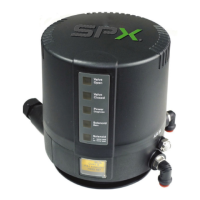
The luminous diodes are located on the front side of the electronic
module. Their signals are visibly indicated to the outside by an
optical window in the cover of the control unit. Beside the open and
closed valve position, the existence of the operating voltage as well
as different diagnostic information are indicated. Chapter 6.6. LED
indication provides more details.
The complete control unit is designed according to the building
block principle. By exchange of the electronic module, the control
typecanbechanged,e.g.fromdirectcontrol(DirectConnect)to
communication with AS-interface.
Note! Wiring must be changed.
 Loading...
